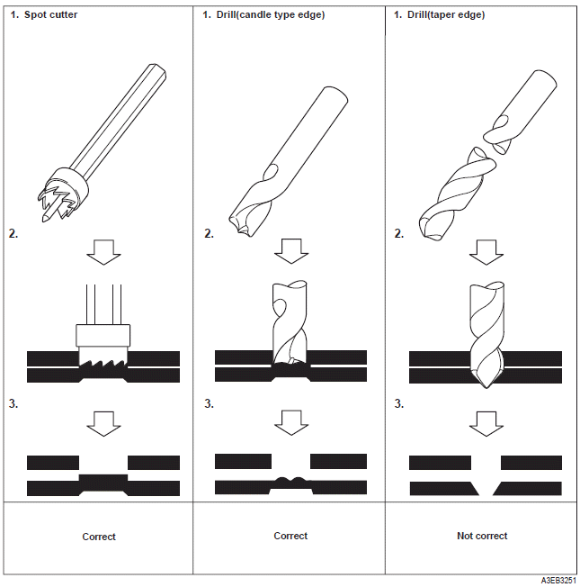
Kia Sportage: Disassembling spot welded area
Most body parts are spot welded. In order to disassemble the damaged area, it is best to disassemble the spot welded area from the body frame using a spot cutter or candle type edge drill bit. Do not use a drill bit with a tapered edge. Center punch middle of spot weld to insure the entire spot weld will be removed.

Assembling a new body frame
The efficiency of the transmission and load distribution are determined by many complicated factors such as thickness of plate, shape and size of a cross section, damage of parts, variance of joints, welding method, and/or welding locations. Therefore, a new part should be fitted to the body frame using the proper procedures to avoid reducing the strength of the body.
Determining a welding method
It is extremely important that appropriate welding methods, which don't reduce the original strength and durability of the body be used when making repairs, Try to use either spot welding or carbon arc (plug) welding, Do not braze any body components other than the ones brazed at the factory. Do not use an oxy-acetylene torch for welding.

READ NEXT:
 Spot welding
1. Commercial spot welding machines do not perform
as well as the machines used in the manufacturing
process. When spot welding, increase the number
of spot welds by 30% (1.3 times the original num
Disassembly - Replacing body panel
Disassembly
1. Body measurement
Before disassembling, measure the damaged area
according to the dimensions supplied in Body
Dimension, Section 31. If deformation is present,
use a frame str
Preparation for assembly - Replacing body panel
Preparation for assembly
1. Spot weld finish
Use a disk grinder or similar tool to finish spot weld
mark. Do not grind more than is necessary to smooth
surface.
2. Panel preparation
Repair any
SEE MORE:
Smart ISG features
Early Engine Restart
If the engine was stopped automatically
by ISG, Early Engine Restart can automatically restart the engine from ISG
without driver action when the vehicle
ahead pulls away and the front view
camera detects the preceding vehicle's
movement.
If the engine restarts au
Schematic Diagrams, Description and Operation
Schematic Diagrams
System Block Diagram
Component Parts And Function Outline
* ETS : Electronic Throttle System
Description and Operation
Cruise Control
The cruise control system is engaged by the cruise "ON/OFF" main switch
located on right of steering wheel
colum
Content
- Home
- Kia Sportage - Fifth generation (NQ5) - (2022-2026) - Owner's Manual
- Kia Sportage - Second generation (JEKM) (2005-2015) - Body Workshop Manual
- Kia Sportage Third generation (SL) - (2011-2016) - Service and Repair Manual
- Sitemap
- Top articles
