Kia Sportage: Disassembly - Replacing body panel
Disassembly
1. Body measurement
- Before disassembling, measure the damaged area according to the dimensions supplied in Body Dimension, Section 31. If deformation is present, use a frame straightener to adjust.
- When disassembling a panel, apply clamps to prevent damage of each part, and support the lower end of the frame to prevent deformation during the procedure.

2. Cut and welding point selection
Cutting, if necessary, should not be done in a reinforcement area. Select an area which will result in the least amount of deformation after welding.

3. Cutting rough area for replacement part
Cutting should be done according to the following steps to make disassembly easy:
- Use care when cutting an area close to a pipe or wiring harness.
- Cut an area leaving 30~50 mm of tolerance.

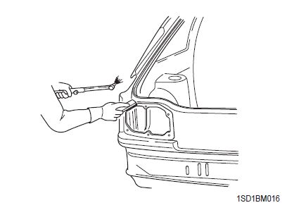
4. Removing paint from an area to be spot welded
Using a torch and wire brush, remove paint completely before beginning welding.

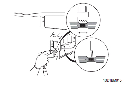
5. Determine a cutting method
- Cutting a spot welded area
Make a hole in the middle of spot welded area with a punch, disassemble welded area using a spot cutter and remove using a chisel.
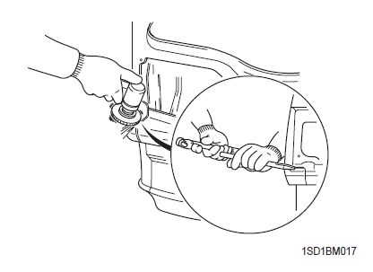
- Removing brazed area
Disassemble using a torch and wire brush, and remove with a chisel.
- Removing arc welded area
Remove plug welded area using a disk grinder and disassemble with a chisel.
READ NEXT:
 Preparation for assembly - Replacing body panel
Preparation for assembly
1. Spot weld finish
Use a disk grinder or similar tool to finish spot weld
mark. Do not grind more than is necessary to smooth
surface.
2. Panel preparation
Repair any
Assembly - Replacing body panel
Assembly
1. Checking welding and fitting in advance
When assembling a new part, measure the
dimensions of each part according to the body
dimensions given in Section 31, and set part to the
Fender apron panel assembly
Welding part
Setion
Cowl panel assembly
Welding part
Section
Dash panel assembly
Welding part
Section
Center floor panel assembly
Welding part
Section
Re
SEE MORE:
Components and Components Location | Rear Glass Defogger Printed Heater
Component Location
Rear glass defogger relay
Rear glass defogger switch
Rear glass defogger
Rear Glass Defogger Printed Heater
Repair procedures
Inspection
CAUTION
Wrap tin foil around the end of the voltmeter test lead to prevent damaging the heater line. Ap
Components and Components Location | Description and Operation
Components
Hands free call switch
Mic
Front left speaker
Front right speaker
Audio head unit (hands free control)
There is no hands free jack. This system supports Ð’luetooth (wireless system).
Description and Operation
Function
Bluetooth Audio
Content
- Home
- Kia Sportage - Fifth generation (NQ5) - (2022-2026) - Owner's Manual
- Kia Sportage - Second generation (JEKM) (2005-2015) - Body Workshop Manual
- Kia Sportage Third generation (SL) - (2011-2016) - Service and Repair Manual
- Sitemap
- Top articles
