Kia Sportage: Start/Stop Button | Fob Holder
Components and Components Location
Component
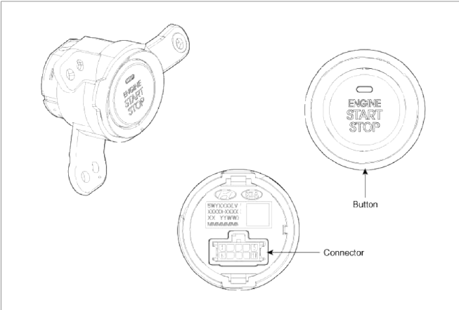
 Connector (10 pins)
- Start stop button switch 1
- LED illumination power
- Amber LED
- Start stop button illumination GND
- Start stop button illumination Power
- Ground
- Start stop button switch 2
- Green LED
- Rheostat
- -
Repair procedures
Removal
1. Disconnect the negative(-) battery terminal.
2. Remove the cluster fascia panel. (Refer to the BD group - "Crash pad")
3. Disconnect the connector (A).
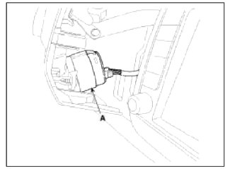
4. Remove the start/stop button (A) after loosening the mounting 3 screws.

Installation
1. Install the start/stop button.
2. Install the left aft vent.
Fob Holder
Components and Components Location
Component
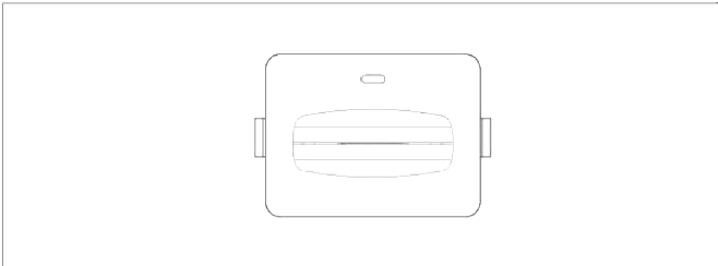
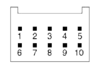 Connector (10 pins)
- -
- Immobilizer dock
- Holder illumination
- GND
- GND
- Battery
- Immobilizer data
- Illumination battery
- Fob in
- -
Repair procedures
Removal
1. Disconnect the negative (-) battery terminal.
2. Remove the floor console. (Refer to the BD group - "Console")
3. Disconnect the connector (B), then remove the fob holder assembly (A) after releasing the hook (C).

Installation
1. Install the fob holder assembly.
2. Install the floor console.
3. Install the negative (-) battery terminal
READ NEXT:
 Ignition Switch Assembly
Repair procedures
Inspection
1. Disconnect the ignition switch connector (B) and key warning switch
connector (A) from under the steering column.
2. Check for continuity between the ter
Back View Camera System
Components and Components Location
Component Location
Back view camera
ECM mirror
Schematic Diagrams
Circuit Diagram
Back view camera connector
Power
Video (+)
Gr
SEE MORE:
Forward Collision-Avoidance Assist malfunction and
limitations
Forward Collision-Avoidance Assist malfunction
Check Forward Safety system
When Forward Collision-Avoidance
Assist is not working properly, the warning
message will appear, and the (
)
and ( ) warning lights will appear
on
the cluster.
Forward Collision-Avoidance Assist disabled
How to reset the power liftgate
If the battery has been discharged or
disconnected, or if the related fuse has
been replaced or disconnected, for the
power liftgate to operate normally, reset
the power liftgate as follow:
Make sure the gear is shifted to P
(Park) position.
Press and hold the Power liftgate
open/close
Content
- Home
- Kia Sportage - Fifth generation (NQ5) - (2022-2025) - Owner's Manual
- Kia Sportage - Second generation (JEKM) (2005-2015) - Body Workshop Manual
- Kia Sportage Third generation (SL) - (2011-2016) - Service and Repair Manual
- Sitemap
- Top articles
