Kia Sportage: Ignition Switch Assembly
Repair procedures
Inspection
1. Disconnect the ignition switch connector (B) and key warning switch connector (A) from under the steering column.
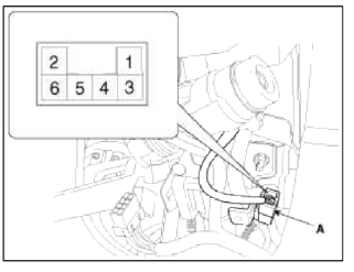

2. Check for continuity between the terminals.
3. If continuity is not specified, replace the switch.

Removal
1. Disconnect the negative (-) battery terminal.
2. Remove the steering column upper and lower shrouds. (Refer to the ST group - "Steering column").
3. Remove the ignition switch (A) after disconnecting the 6P connector (B).

4. Remove the key warning and immobilizer connector (A).

5. Remove the key illumination cover.
6. If it is necessary to remove the key lock cylinder (A), remove the key lock cylinder after pushing lock pin (B) with key ACC.

Installation
1. Install the key lock cylinder.
2. Install the illumination cover.
3. Install the key warning and immobilizer connector.
4. Install the ignition switch.
5. Install the steering column shrouds and crash pad lower panel.
READ NEXT:
 Back View Camera System
Components and Components Location
Component Location
Back view camera
ECM mirror
Schematic Diagrams
Circuit Diagram
Back view camera connector
Power
Video (+)
Gr
General Information
Specifications
Specifications
NOTE
O.D. : Outer Diameter
I.D. : Inner Diameter
Specification (ESC)
Service Standard
Tightening Torques
Lubricants
Special Service Tools
&nbs
SEE MORE:
Driving on grades
Reduce the speed and shift to a lower
gear before you start down a long or
steep downgrade. If you don't shift
down, you might have to use your
brakes so much that they would get hot
and no longer operate efficiently.
On a long uphill grade, shift down and
reduce your speed to around 45
Components and Components Location
Components Location
Converter housing
Automatic transaxle case
Rear cover
Valve body cover
Manual control lever
Air breather hose
Inhibitor switch
Solenoid valve
connector
Repair procedures
Removal
1. Remove the following items;
Engine cover (A).
Air cleaner asse
Content
- Home
- Kia Sportage - Fifth generation (NQ5) - (2022-2026) - Owner's Manual
- Kia Sportage - Second generation (JEKM) (2005-2015) - Body Workshop Manual
- Kia Sportage Third generation (SL) - (2011-2016) - Service and Repair Manual
- Sitemap
- Top articles
