Kia Sportage: Back View Camera System
Components and Components Location
Component Location
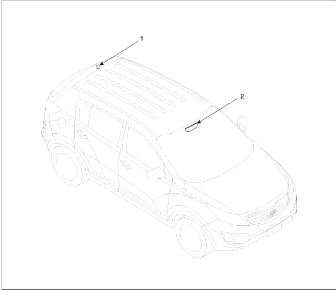
- Back view camera
- ECM mirror
Schematic Diagrams
Circuit Diagram
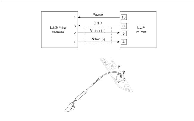
 Back view camera connector
- Power
- Video (+)
- Ground
- Video (-)
Description and Operation
Description
Back view camera will activate when the backup light is ON with the ignition switch ON and the shift lever in the R position.
This system is a supplemental system that shows behind the vehicle through the ECM (Reverse Display Room Mirror) mirror or the Navigation unit while backing-up.
WARNING
This system is a supplementary function only. It is the responsibility of the driver or always check the inside/ outside rearview mirror and the area behind the vehicle before and while backing up because there is a dead zone that can't see through the camera.
Repair procedures
Removal
1. Remove the tailgate trim in the trunk after removing the screws and clips. (Refer to the BD group - "Tailgate")
2. Remove the tailgate garnish (A) after disconnecting the connector and removing the bolts.

3. Remove the back view camera (A) after loosening the screws (2EA).

Installation
1. Install the back view camera.
2. Install the tailgate garnish and trim.
READ NEXT:
 General Information
Specifications
Specifications
NOTE
O.D. : Outer Diameter
I.D. : Inner Diameter
Specification (ESC)
Service Standard
Tightening Torques
Lubricants
Special Service Tools
&nbs
SEE MORE:
Key positions
Your vehicle is equipped with four different
ignition positions.
Illuminated ignition switch
Whenever a front door is opened, the
ignition switch will illuminate for your
convenience, provided the ignition
switch is not in the ON position.
The light will go off immediately when
the ignit
Valve Body
Description and Operation
Description
The valve body is essential to automatic transaxle control and consists of
various valves used to control the oil feed
from the oil pump. Specifically, these valves consist of pressure regulator
valves, oil redirection valves, shift valves,
and man
Content
- Home
- Kia Sportage - Fifth generation (NQ5) - (2022-2025) - Owner's Manual
- Kia Sportage - Second generation (JEKM) (2005-2015) - Body Workshop Manual
- Kia Sportage Third generation (SL) - (2011-2016) - Service and Repair Manual
- Sitemap
- Top articles
