Kia Sportage: Oil Cooler | Oil Pressure Switch
Repair procedures
Removal
1. Loosen the drain plug, and drain the coolant. Remove the radiator cap to speed draining.
2. Disconnect the oil cooler coolant hoses (A).

З. Remove the oil filter (A).

4. Loosen the mounting bolt (A) and remove the oil cooler assembly (B).
Installation
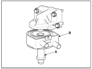
1. Apply a light coat of engine oil to the oil cooler packing surface (A), and then install the oil cooler with fix bolt (B).
Tightening torque: 44.1 ~ 53.9 N.m (4.5 ~ 5.5 kgf.m, 32.5 ~ 39.8 lb-ft)

CAUTION
Fix position of oil cooler stopper (A) where oil cooler resists on ladder frame stopper (B).

2. Apply a light coat of engine oil to the oil filter packing surface (A), and then install the oil filter.
Tightening torque: 11.8 ~ 15.7 N.m (1.2 ~ 1.6 kgf.m, 8.7 ~ 11.6 lb-ft)
3. Connect the oil cooler coolant hoses (B).

4. Fill the radiator with coolant and check for leaks.
Oil Pressure Switch
Repair procedures
Inspection
1. Check the continuity between the terminal and the body with an ohmmeter.
If there is no continuity, replace the oil pressure switch.

2. Check the continuity between the terminal and the body when the fine wire is pushed. If there is continuity even when the fine wire is pushed, replace the switch.
3. If there is no continuity when a 50kPa (0.50kgf/cm2,7.25psi) is applied through the oil hole, the switch is operating properly.
Check for air leakage. If air leaks, the diaphragm is broken. Replace it.

READ NEXT:
 Intake Manifold
Components and
Components Location
Components
Intake manifold
assembly
Electronic throttle body
Intake manifold stay
Intake manifold gasket
Repair procedures
Removal and Inst
SEE MORE:
Vehicle lift (2-Support type) and safety stand positions
1. Place the lift blocks under the support points as shown in the
illustration.
2. Raise the hoist a few inches and rock the vehicle to be sure it is firmly
supported.
3. Raise the hoist to full height to inspect the lift points for secure support.
Jack and safety stand positions
Towin
Warning lights
The warning light and indicator light
indicate a situation where the driver
should be careful and whether the various
functions are activated.
Warning lights
The warning light indicates situations
that require the driver to pay attention
NOTICE
Warning lights
Make sure that all warning lig
Content
- Home
- Kia Sportage - Fifth generation (NQ5) - (2022-2026) - Owner's Manual
- Kia Sportage - Second generation (JEKM) (2005-2015) - Body Workshop Manual
- Kia Sportage Third generation (SL) - (2011-2016) - Service and Repair Manual
- Sitemap
- Top articles
