Kia Sportage: Intake Manifold
Components and Components Location
Components
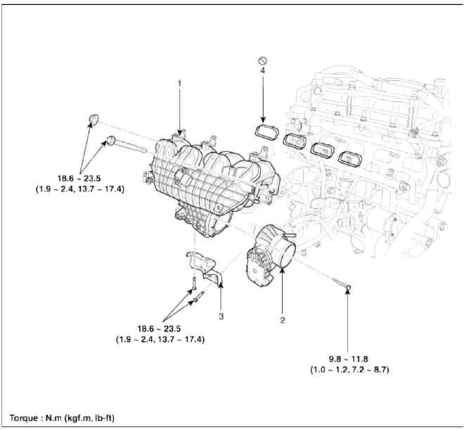
- Intake manifold assembly
- Electronic throttle body
- Intake manifold stay
- Intake manifold gasket
Repair procedures
Removal and Installation
1. Remove the engine cover.
2. Disconnect the battery negative terminal (A).
Tightening torque 4.0 ~ 6.0N.m (0.4 ~ 0.6kgf.m, 3.0 ~ 4.4lb-ft)

3. Remove the air cleaner assembly.
- Remove the air duct (A).
- Disconnect the breather hose (B), the recirculation hose (C) and brake booster vacuum hose (D).
- Disconnect the air intake hose (E) and then remove the air cleaner assembly (F).
Tightening torque
Hose clamp bolt: 2.9 ~ 4.9N.m (0.3 ~ 0.5kgf.m, 2.2 ~ 3.6lb-ft)
Air cleaner assembly bolts: 7.8 ~ 9.8N.m (0.8 ~ 1.0kgf.m, 5.8 ~ 7.2lb-ft)

4. Disconnect the recirculation valve connector (A) and the vacuum hose (B), and then remove the intercooler inlet pipe & hose assembly (C).
Tightening torque
Hose clamp bolt: 4.9 ~ 6.9 N.m (0.5 ~ 0.7 kgf.m, 3.6 ~ 5.1 lb-ft)
Pipe mounting bolt: 14.7 ~ 19.6 N.m (1.5 ~ 2.0 kgf.m, 10.8 ~ 14.5 lb-ft)

5. Disconnect the boost pressure sensor connector (A) and then remove the intercooler outlet pipe & hose assembly (B).
Tightening torque 4.9 ~ 6.9 N.m (0.5 ~ 0.7 kgf.m, 3.6 ~ 5.1 lb-ft)

6. Remove the under cover (A).
Tightening torque: 9.8 ~ 11.8 N.m (1.0 ~ 1.2 kgf.m, 7.2 ~ 8.7 lb-ft)

7. Loosen the drain plug, and drain the engine coolant. Remove the radiator cap to drain with speed. (Refer to Cooling system in this group) 8. Disconnect the PCV hose (A), the intake OCV (Oil control valve) connector (B) and the OTS (Oil temperature sensor) connector (C).

9. Disconnect the Ð/С compressor switch connector (A), the alternator connector (B), the OPS (Oil pressure switch) connector & injector extension connector (C), the knock sensor connector (D), the MAPS (Manifold absolute pressure sensor) & LAPS (Intake air temperature sensor) connector (E), the ETC (Electronic throttle control) connector (F) and the vacuum pump connector (G).

10. Disconnect the throttle body coolant hoses (A).

11. Remove the oil level gauge (A).

12. Remove the intake manifold stay (A).
Tightening torque: 18.6 ~ 23.5N.m (1.9 ~ 2.4kgf.m, 13.7 ~ 17.4lb-ft)

13. Remove the intake manifold (A) after disconnecting the vacuum hoses.
Tightening torque: 18.6 ~ 23.5N.m (1.9 ~ 2.4kgf.m, 13.7 ~ 17.4lb-ft)

NOTE
When installing, replace with new gaskets.
When installing the intake manifold, tighten the bolts and nuts with pre-torque first, and then tighten the bolts and nuts with specified torque in the sequence shown.

14. Installation is reverse order of removal.
READ NEXT:
 Exhaust Manifold
Components and
Components Location
Components
Hear protector
EWGA (Electric Waste Gate
Actuator)
C-ring
Turbo manifold module
Turbocharger stay
Turbo adapter gasket
Turbo a
Turbo Charger
Components and
Components Location
Components
Turbine housing
Turbine inlet
Turbine outlet
Compressor housing
Compressor inlet
Compressor outlet
Center housing
EWGA (Electr
Intercooler
Components and
Components Location
Components
Recirculation hose
Intercooler inlet hose & pipe
assembly
Intercooler outlet hose & pipe
assembly
Intercooler mounting bra
SEE MORE:
Reverse Parking Collision-Avoidance
Assist malfunction and limitations
Reverse Parking Collision-Avoidance Assist malfunction
A: Check Parking Safety system
When Reverse Parking Collision-Avoidance
Assist or other related functions
are not working properly, the warning
message will appear on the cluster, and
Reverse Parking Collision-Avoidance
Assist will tu
Emission control system
The emission control system of your
vehicle is covered by a written limited
warranty. Please see the warranty information
contained in the Warranty &
Consumer Information manual in your
vehicle.
Your vehicle is equipped with an emission
control system to meet all applicable
emission re
Content
- Home
- Kia Sportage - Fifth generation (NQ5) - (2022-2026) - Owner's Manual
- Kia Sportage - Second generation (JEKM) (2005-2015) - Body Workshop Manual
- Kia Sportage Third generation (SL) - (2011-2016) - Service and Repair Manual
- Sitemap
- Top articles
