Kia Sportage: Master Cylinder
Components and Components Location
Components
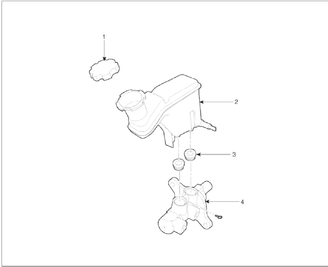
- Reservoir cap
- Reservoir'
- Grommet
- Master cylinder
Repair procedures
Removal
1. Turn ignition switch OFF and disconnect the negative (-) battery cable.
2. Disconnect the battery terminal and then remove the battery.

3. Disconnect the ECM connector and the ECM and battery tray.
4. Disconnect the brake fluid level switch connector (A), and remove the reservoir cap.

5. Remove the brake fluid from the master cylinder reservoir with a syringe.
CAUTION
- Be sure to completely remove foreign substances from around brake fluid reservoir and cap before opening the reservoir cap. If not, it may cause contamination of brake fluid and deterioration in braking performance.
- Do not spill brake fluid on the vehicle, it may damage the paint; if brake fluid does contact the paint, wash it off immediately with water.
6. Disconnect the brake tube (A) from the master cylinder by loosening the tube flare nut.
Tightening torque: 16.7 ~ 22.6N.m (1.7 ~ 2.3kgfm, 12.3 ~ 16.6lb-ft)

7. Remove the master cylinder (B) from the brake booster after loosening the mounting nuts (A).
Tightening torque: 7.9 ~ 11.8N.m (0.8 ~ 1.2kgf.m, 5.8 ~ 8.7lb-ft)

Installation
1. Installation is the reverse of removal.
2. After installation, bleed the brake system. (Refer to Brake system bleeding).
READ NEXT:
 Brake Line
Components and Components Location
Components
Repair procedures
Removal
1. Disconnect the brake fluid level switch connector, and remove the
reservoir cap.
2. Remove the brake fluid f
Brake Pedal
Components and Components Location
Components
Cowl bracket
Brake pedal member assembly
Stop lamp switch
Return spring
Brake pedal stopper
Clevis pin
Snap pin
Brake pedal
Front Disc Brake
Components and Components Location
Components
Guide rod bolt
Bleed screw
Caliper bracket
Caliper body
Inner pad shim
Brake pad
Pad retainer
Repair procedures
Removal
1. R
SEE MORE:
Towing
Towing service
If emergency towing is necessary, have
it done by authorized Kia dealer or a
commercial tow-truck service.
Proper lifting and towing procedures are
necessary to prevent damage to the
vehicle. The use of wheel dollies (1) or
flatbed is recommended.
CAUTION
The AWD vehicl
Operating high beam
Operating high beam
To turn on the high beam headlamp:
Push the lever away from you.
The lever will return to its original
position.
The high beam indicator will light
when the headlamp high beams are
switched on.
WARNING
High beams
Do not use high beam when there are
oth
Content
- Home
- Kia Sportage - Fifth generation (NQ5) - (2022-2025) - Owner's Manual
- Kia Sportage - Second generation (JEKM) (2005-2015) - Body Workshop Manual
- Kia Sportage Third generation (SL) - (2011-2016) - Service and Repair Manual
- Sitemap
- Top articles
