Kia Sportage: Front Disc Brake
Components and Components Location
Components
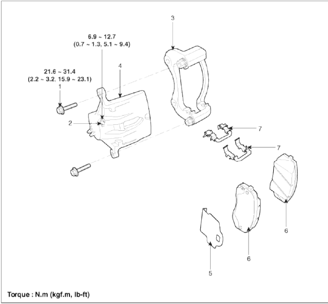
- Guide rod bolt
- Bleed screw
- Caliper bracket
- Caliper body
- Inner pad shim
- Brake pad
- Pad retainer
Repair procedures
Removal
1. Remove the front wheel & tire.
Tightening torque: 88.3 ~ 107.9 N.m (9.0 ~ 11.0 kgf.m, 65.1 ~ 79.6 lb-ft)
2. Loosen the hose eyebolt (B) and caliper mounting bolts (C), then remove the front caliper assembly (A).
Tightening torque:
Brake hose to caliper (B): 24.5 ~ 29.4 N.m (2.5 ~ 3.0 kgf.m, 18.1 ~ 21.7 lb-ft)
Caliper assembly to knuckle (C): 78.5 ~ 98.1 N.m (8.0 ~ 10.0 kgf.m, 57.9 ~ 72.3 lb-ft)

3. Remove the front brake disc by loosening the screws (A).

Replacement
Front brake pads
1. Remove the brake hose mounting bracket bolt (A).

2. Loosen the guide rod bolt (B) and pivot the caliper (A) up out of the way.
Tightening torque: 21.6 ~ 31.4 N.m (2.2 ~ 3.2 kgf.m, 15.9 ~ 23.1 lb-ft)

3. Replace pad shim (D), pad retainers (C) and brake pads (B) in the caliper bracket (A).

Inspection
Front brake disc thickness check
1. Check the brake pads for wear and fade.
2. Check the brake disc for damage and cracks.
3. Remove all rust and contamination from the surface, and measure the disc thickness at 8 points, at least, of same distance (5mm) from the brake disc outer circle.
Brake disc thickness
[2WD]
- Standard : 26 mm (1.02 in)
- Service Limit: 24.4 mm (0.96 in)
[4WD]
- Standard : 28 mm (1.10 in)
- Service Limit: 26.4 mm (1.04 in)
Deviation: Less than 0.005 mm (0.0002 in)

4. If wear exceeds the limit, replace the discs arid pad assembly left and right of the vehicle.
Front Brake Pad Check
1. Check the pad wear. Measure the pad thickness and replace it, if it is less than the specified value.
Pad thickness
Standard value: 11 mm (0.43 in)
Service limit: 2.0 mm (0.0787 in)
2. Check that grease is applied, to sliding contact points and the pad and backing metal for damage.

Front brake disc runout check
1. Place a dial gauge about 5mm (0.2 in.) from the outer circumference of the brake disc, and measure the runout of the disc.
Brake disc runout
Limit: 0.025 mm (0.00098 in.) or less (new one)

2. If the runout of the brake disc exceeds the limit specification, replace the disc, and then measure the runout again.
3. If the runout does not exceed the limit specification, install the brake disc after turning it 180º and then check the runout of the brake disc again.
4. If the runout cannot be collected by changing the position of the brake disc, replace the brake disc.
Installation
1. Installation is the reverse of removal.
2. Use a SST (09581-11000) when installing the brake caliper assembly.

3. After installation, bleed the brake system. (Refer to Brake system bleeding)
READ NEXT:
 Rear Disc Brake
Components and Components Location
Components
Guide rod bolt
Bleed screw
Caliper bracket
Caliper body
Inner pad shim
Brake pad
Pad retainer
Repair procedures
Removal
1. R
Components and ComponentsLocation | Removal - Repair procedures
Components (1)
[Hand Type] / [Foot Type]
Parking brake pedal assembly
Front parking brake cable (Foot type only)
Equalizer assembly
Rear parking brake cable
Parkin
SEE MORE:
Forward Collision-Avoidance Assist operation
The basic function for Forward Collision-
Avoidance Assist is warned and controlled
by the following level.
Collision Warning
Emergency Braking
Stopping vehicle and ending brake
control
Collision Warning
Collision Warning
The warning message, and an audible
warning will wa
Heated steering wheel
When the ignition switch or ENGINE
START/STOP button is in the ON position,
pressing the heated steering wheel
button warms the steering wheel. The
indicator on the button will illuminate.
To turn the heated steering wheel off,
press the button once again. The indicator
on the button will
Content
- Home
- Kia Sportage - Fifth generation (NQ5) - (2022-2026) - Owner's Manual
- Kia Sportage - Second generation (JEKM) (2005-2015) - Body Workshop Manual
- Kia Sportage Third generation (SL) - (2011-2016) - Service and Repair Manual
- Sitemap
- Top articles
