Kia Sportage: Brake Pedal
Components and Components Location
Components
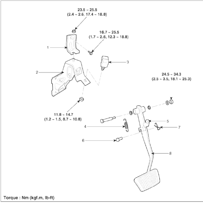
- Cowl bracket
- Brake pedal member assembly
- Stop lamp switch
- Return spring
- Brake pedal stopper
- Clevis pin
- Snap pin
- Brake pedal
Repair procedures
Removal
1. Remove the crash pad lower panel and reinforcement panel. (Refer to the Body group- crash pad).
2. Pull down steering column shaft after removing bolts and nuts.
З. Disconnect the stop lamp switch connector (A).

4. Remove the brake pedal member mounting nut (B).
Tightening torque: 16.5 ~ 25.5 N.m (1.7 ~ 2.6 kgf.m, 12.3 ~ 18.8 lb-ft)
5. Remove the snap pin (A) and clevis pin (B).

6. Remove the brake pedal member assembly mounting nuts and then remove the brake pedal assembly.
Tightening torque: 16.7 ~ 25.5 N.m (1.7 ~2.6 kgf.m, 12.3 ~ 18.8 lb-ft)

7. Remove the cowl bracket (A).
Tightening torque: 23.5 ~ 25.5 N.m (2.4 ~2.6 kgf.m, 17.4 ~ 18.8 lb-ft)

Inspection
1. Check the bushing for wear.
2. Check the brake pedal for bending or twisting.
3. Check the brake pedal return spring for damage.
4. Check the stop lamp switch.
- Connect a circuit tester to the connector of stop lamp switch, and check whether or not there is continuity when the plunger of the stop lamp switch is pushed in and when it is released.
- The stop lamp switch is in good condition if there is no continuity when plunger (A) is pushed.

Installation
1. Installation is the reverse of removal.
CAUTION
- Before installing the pin, apply the grease to the clevis pin.
- Use a new snap pin whenever installing.
2. Adjust the brake pedal height and flee play.
3. Check the brake pedal operation.
Adjustment
Brake Pedal Height and Free Play
1. Disconnect the stop lamp switch connector (A) and loosen the stop lamp switch lock nut.

2. Adjust the brake pedal height (A) as illustration below.
Pedal height (A): 165 mm (6.50 in)
Full stroke (C ): 135 mm (5.31 in)

3. Adjust the stop lamp switch clearance (B) and brake pedal free play.
Stop lamp clearance: 1.5 ~ 2.0 mm (0.06 ~ 0.08 in)
Pedal free play: 3.0 ~ 8.0 mm (0.12 ~ 0.31 in)
4. Connect the stop lamp switch connector.
READ NEXT:
 Front Disc Brake
Components and Components Location
Components
Guide rod bolt
Bleed screw
Caliper bracket
Caliper body
Inner pad shim
Brake pad
Pad retainer
Repair procedures
Removal
1. R
Rear Disc Brake
Components and Components Location
Components
Guide rod bolt
Bleed screw
Caliper bracket
Caliper body
Inner pad shim
Brake pad
Pad retainer
Repair procedures
Removal
1. R
SEE MORE:
Side Impact Sensor (SIS)
Description and Operation
Description
Side Impact Sensor (SIS) system consists of two P-SIS which are installed at
each center of the front door module
(LH and RH) and two SIS which are installed at each center pillar nearby (LH and
RH).
Side Pressure Sensor is also called P-SIS beca
Intake Air Temperature Sensor (IATS) | Engine Coolant Temperature Sensor (ECTS)
Description and Operation
Description
Intake Air Temperature Sensor (IATS) is included inside Manifold Absolute Pressure Sensor and detects the intake air temperature.
To calculate precise air quantity, collection of the air temperature is needed because air density varies according to th
Content
- Home
- Kia Sportage - Fifth generation (NQ5) - (2022-2025) - Owner's Manual
- Kia Sportage - Second generation (JEKM) (2005-2015) - Body Workshop Manual
- Kia Sportage Third generation (SL) - (2011-2016) - Service and Repair Manual
- Sitemap
- Top articles
