Kia Sportage: Intercooler
Components and Components Location
Components
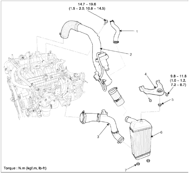
- Recirculation hose
- Intercooler inlet hose & pipe assembly
- Intercooler outlet hose & pipe assembly
- Intercooler mounting bracket
- Intercooler upper mounting insulator
- Intercooler
- Intercooler lower mounting insulator
Repair procedures
Removal and Installation
1. Disconnect the battery negative terminal (A).
Tightening torque 4.0 ~ 6.0N.m (0.4 ~ 0.6kgf.m, 3.0 ~ 4.4lb-ft)

2. Remove the air cleaner assembly.
- Remove the air duct (A).
- Disconnect the breather hose (B), the recirculation hose (C) and the brake booster vacuum hose (D).
- Disconnect the air intake hose (E) and then remove the air cleaner assembly (F).
Tightening torque
Hose clamp bolt: 2.9 ~ 4.9N.m (0.3 ~ 0.5kgf.m, 2.2 ~ 3.6lb-ft)
Air cleaner assembly bolts: 7.8 ~ 9.8N.m (0.8 ~ l.0kgf.m, 5.8 ~ 7.2lb-ft)

3. Disconnect the recirculation valve connector (A) and the vacuum hose (B), and then remove the intercooler inlet pipe assembly (C).

4. Disconnect the boost pressure sensor connector (A) and then remove the intercooler outlet pipe & hose assembly (B).
Tightening torque 4.9 ~ 6.9 N.m (0.5 ~ 0.7 kgf.m 3.6 ~ 5.1 lb-ft)

5. Remove the under cover (A).
Tightening torque: 9.8 ~ 11.8 N.m (1.0 ~ 1.2 kgf.m, 7.2 ~ 8.7 lb-ft)

6. Remove the front bumper. (Refer to BD group)
7. Remove the front bumper upper stiffner (A).

8. Remove the radiator upper cover (A).

9. Remove the intercooler upper mounting bracket (A) and then remove the intercooler (B).
Tightening torque 9.8 ~ 11.8 N.m (1.0 ~ 1.2 kgf.m, 7.2 ~ 8.7 lb-ft)

10. Installation is reverse order of removal.
READ NEXT:
 Muffler
Components and Components
Location
Components
Front muffler
Catalytic converter
Center muffler
Main muffler
Gasket
Repair procedures
Removal and Installation
1. Remove the f
SEE MORE:
Components and Components Location | Compressor Oil
Component Location Index
Engine Room
Condenser
Receiver-drier
Compressor
Expansion Valve
Service port (High)
Service port (Low)
Ð/С Pressure
Transducer
Interior
Compressor Oil
Repair procedures
Oil Specification
1. The HFC-134a system
Transmission overheated
Transmission Hot! Park with engine
on
Trans cooled. Resume driving
When driving on muddy and sandy
roads under the severe condition, the
transmission could be overheated.
When the transmission is overheated,
the safe protection mode engages
and the "Transmission Ho
Content
- Home
- Kia Sportage - Fifth generation (NQ5) - (2022-2026) - Owner's Manual
- Kia Sportage - Second generation (JEKM) (2005-2015) - Body Workshop Manual
- Kia Sportage Third generation (SL) - (2011-2016) - Service and Repair Manual
- Sitemap
- Top articles
