Kia Sportage: Balance Shaft & Oil Pump
Components and Components Location
Components
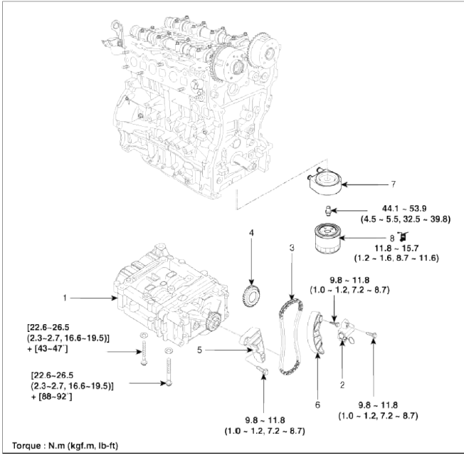
- Balance shaft & oil pump assembly
- Balance shaft chain tensioner
- Balance shaft chain
- Balance shaft chain sprocket
- Balance shaft chain guide
- Balance shaft chain tensioner arm
- Oil cooler
- Oil filter
Repair procedures
Removal
1. Remove the timing chain. (Refer to Timing system in this group)
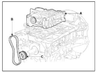
2. Install a stopper pin (A) after compressing the balance shaft chain tensioner.
3. Remove the balance shaft chain hydraulic tensioner (B).
4. Remove the balance shaft chain tensioner arm (C).
5. Remove the balance shaft chain guide (D).

6. Remove the balance shaft & oil pump module (A) and balance shaft chain (B) and the sprocket (C).
CAUTION
Do not disassemble the balance shaft & oil pump module.
Installation
1. The key of crankshaft should be aligned with the mating face of main bearing cap. As a result of this, the piston of No.1 cylinder is placed at the top dead center on compression stroke.
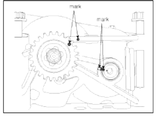
2. Confirm the balance shaft & oil pump module timing mark.
Timing marks to be visually aligned with centers of adjacent cast timing notches.
З. Install the balance shaft & oil pump module (A) with the chain (B) and the sprocket (C).

NOTE
The timing marks of balance shaft & oil pump module sprocket and crankshaft sprocket should be matched with the tuning marks (color link) of balance shaft chain.

Tightening order
- Tighten the bolts in order number as shown with seating torque 26.4 N.m (3.0kgf.m, 21.7 lb-ft) and then loosen the bolts as reverse tightening order. (6-5-4-3-2-1).
- Using the SST (09221-4A000), tighten the bolts as specified tightening order in same increments as follows.
Tightening torque:
Bolts (A) (M9x181.5): 22.6-26.5N.m (2.3~2.7kgf.m, 16.6~19.5lb-ft) + 88~92º
Bolts (B) (M9x95): 22.6~26.5N.m (2.3~2.7kgf.m, 16.6~19.5lb-ft) + 43~47º

4. Install the balance shaft chain guide (D).
Tightening torque: 9.8 ~ 11.8N.m (1.0 ~ 1.2kgf.m, 7.2 ~ 8.7lb-ft)
5. Install the balance shaft chain tensioner arm (C).
Tightening torque: 9.8 ~ 11.8N.m (1.0 ~ 1.2kgf.m, 7.2 ~ 8.7lb-ft)
6. Install the balance shaft chain hydraulic tensioner (B) then remove the stopper pin (A).
Tightening torque: 9.8 ~ 11.8N.m (1.0 ~ 1.2kgf.m, 7.2 ~ 8.7lb-ft)

7. Confirm the timing marks.
8. Install the timing chain. (Refer to Timing system in this group)
READ NEXT:
 Oil Cooler | Oil Pressure Switch
Repair procedures
Removal
1. Loosen the drain plug, and drain the coolant. Remove the radiator cap to speed draining.
2. Disconnect the oil cooler coolant hoses (A).
З. Remove the oil f
SEE MORE:
Blind-Spot Collision-Avoidance Assist operation
Blind-Spot Collision-Avoidance Assist
will warn and control as following operation.
Vehicle detection
Collision Warning
Collision-Avoidance Assist
Vehicle detection
Warning light will appear in the outside
rear view mirror when the vehicle on
both lanes is detected from the rear.
Towing
If the vehicle needs to be towed, call a professional towing service. Never
tow vehicle with just a rope or chain. It is
very dangerous.
Emergency Towing
There are three popular methods of towing a vehicle:
The operator loads the vehicle on the back of truck. This is best way of
tran
Content
- Home
- Kia Sportage - Fifth generation (NQ5) - (2022-2026) - Owner's Manual
- Kia Sportage - Second generation (JEKM) (2005-2015) - Body Workshop Manual
- Kia Sportage Third generation (SL) - (2011-2016) - Service and Repair Manual
- Sitemap
- Top articles
