Kia Sportage: Horn
Components and Components Location
Component Location
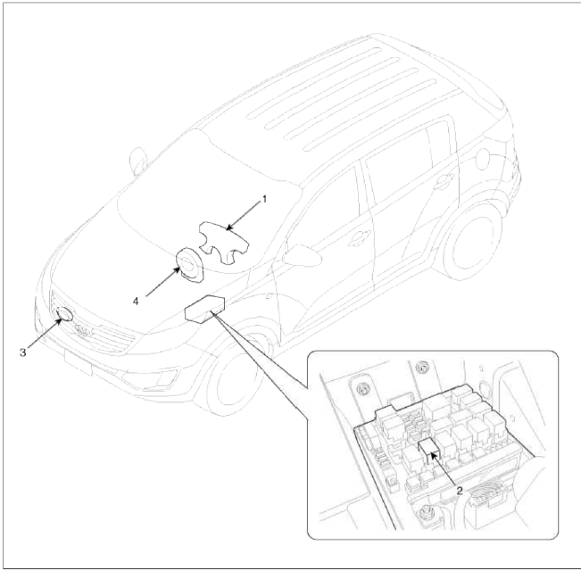
- Horn switch
- Horn relay (Engine room compartment)
- Horn (Low pitch)
- Clock spring
Repair procedures
Removal
1. Remove the radiator upper cover.
(Refer to the BD group - "Front bumper")
2. Remove the bolt and disconnect the horn connector, then remove the low pitch horn (A).

Installation
1. Install the horn after connecting the horn connector.
2. Install the radiator upper cover.
Inspection
Test the horn by connecting battery voltage to the 1 terminal and ground the 2 terminal.
The horn should make a sound. If the horn fails to make a sound, replace it.
Horn Relay Inspection
1. Remove the horn relay (A) from the engine room relay box.
2. There should be continuity between the No.30 and No.87 terminals when power and ground are connected to the No.85 and No.86 terminals.
3. There should be no continuity between the No.30 and No.87 terminals when power is disconnected.

Adjustment
1. Operate the horn, and adjust the tone to a suitable level by tinning the adjusting screw.
NOTE
Horn adjustment screw is automatically sealed with silicon sealant.
The shape and size of the applied sealant is variable and tails or dribbles are acceptable and not to be tampered with.

READ NEXT:
 Specifications, Components and Components Location
Specifications
Specifications
Display System
DVD Deck
Bluetooth
Storage Memory
Components and Components Location
Component Location
AVN (A/V & Navigation) head
Description and Operation
Limitations Of The Navigation system
GPS Signal Reception State
As the GPS satellite frequency is received/transmitted in straight lines,
reception may not work if hiding devices are
placed
SEE MORE:
Ignition System
Description and Operation
Description
Ignition timing is controlled by the electronic control ignition timing
system. The standard reference ignition timing
data for the engine operating conditions are preprogrammed in the memory of the
ECM (Engine Control Module).
The engine operati
Operating HomeLink
Operating HomeLink
1) Operating HomeLink
Press and release the desired programmed
HomeLink button (1, 2 or 3).
NOTICE
The HomeLink indicator (7) should light
green, solid or flashing, and your programmed
device should operate.
If your device does not operate, the
HomeLink prog
Content
- Home
- Kia Sportage - Fifth generation (NQ5) - (2022-2026) - Owner's Manual
- Kia Sportage - Second generation (JEKM) (2005-2015) - Body Workshop Manual
- Kia Sportage Third generation (SL) - (2011-2016) - Service and Repair Manual
- Sitemap
- Top articles
