Kia Sportage: Cruise Control Switch
Schematic Diagrams
Circuit Diagram
[Auto Cruise Control]
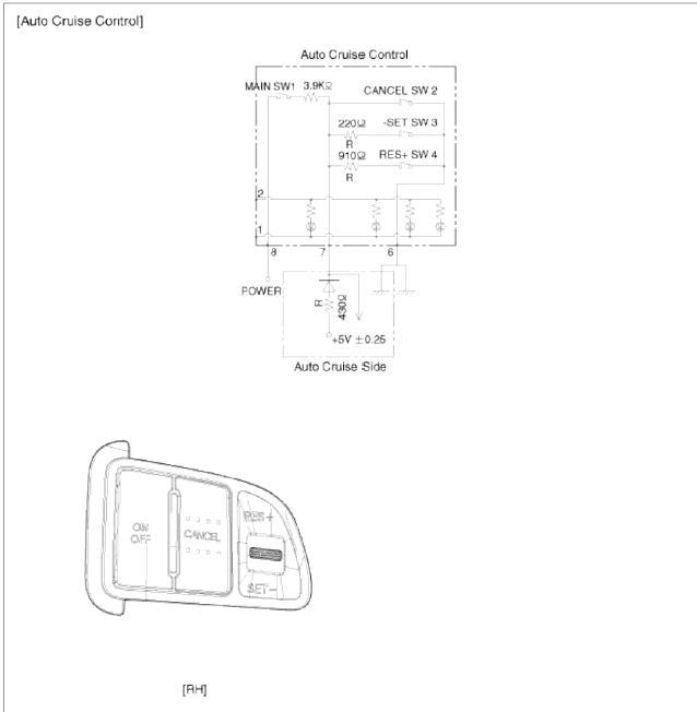
 Connector RH
- ILL (-)
- ILL (+)
- -
- -
- -
- ACC GND
- ACC signal
- ACC power
Repair procedures
Removal and Installation
1. Disconnect the battery (-) terminal.
Tightening torque:
Without battery sensor: 7.8 ~ 9.8N.m (0.8 ~ 1.0.kgf.m, 5.8 ~ 7.2lb-ft)
With battery sensor: 4.0 ~ 6.0N.m (0.4 ~ 0.6kgf.m, 3.0 ~ 4.4lb-ft)
2. Remove the airbag module from the steering wheel. (Refer to RT group)
3. Remove the steering wheel. (Refer to ST group)
4. Remove the cruise control switch (A) after unfastening the 2 screws and disconnecting the switch connector.

5. Installation is reverse order of removal.
Inspection
Measuring Resistance
1. Disconnect the cruise control switch connector from the control switch.

2. Measure resistance between terminals on the control switch when each function switch is ON (switch is depressed).

3. If not within specification, replace switch.
Measuring Voltage
1. Connect the cruise control switch connector to the control switch.
2. Measure voltage between terminals on the harness side connector when each function switch is ON (switch is depressed).

3. If not within specification, inspect the control switch resistance.
The measuring resistance value is not within specification, replace the switch and measure the voltage again.
4. If resistance is OK but, measuring voltage is not within specification, inspect the wiring harness and connectors between the switch and the ECM.
READ NEXT:
 General Information
Specifications
Specifications
Tightening Torques
Repair procedures
Compression Pressure Inspection
NOTE
If the there is lack of power, excessive oil consumption or poor
Engine And Transaxle Assembly
Engine Mounting
Components and
Components Location
Components
Transaxle mounting bracket
Roll rod bracket
Sub frame
Engine mounting bracket
Engine mounting support
bracket
SEE MORE:
Indicator lights
Electronic stability control (ESC)
indicator light
This indicator light appears:
Once you set the ignition switch or
ENGINE START/STOP Button to the
ON position.
It appears for approximately 3 seconds
and then goes off.
When there is a malfunction with the
ESC system.
In
Drive mode integrated control system
Drive mode
The drive mode may be selected according
to the driver's preference or road
condition.
Type A
Type B
Type C
The Drive mode is activated by turning
the knob.
NOTICE
If there is a problem with the instrument
cluster, the drive mode will be in NORMAL
mode and may
Content
- Home
- Kia Sportage - Fifth generation (NQ5) - (2022-2025) - Owner's Manual
- Kia Sportage - Second generation (JEKM) (2005-2015) - Body Workshop Manual
- Kia Sportage Third generation (SL) - (2011-2016) - Service and Repair Manual
- Sitemap
- Top articles
