Kia Sportage: Alternator
Components and Components Location
Components
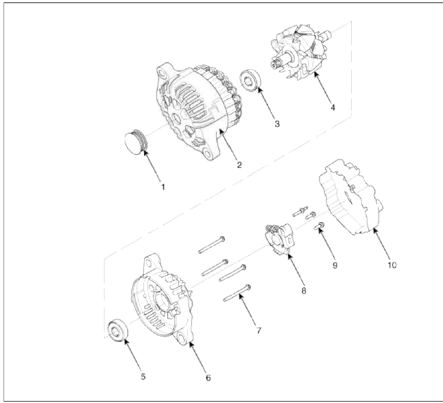
- Pulley
- Front bracket
- Front bearing
- Rotor
- Rear bearing
- Rear bracket
- Though bolt
- Regulator assembly
- Regulator bolt
- Rear cover
Repair procedures
Removal and Installation
1. Disconnect the battery negative terminal first, then the positive terminal.
Tightening torque:
(+) terminal: 7.8 ~ 9.8N.m (0.8 ~ 1.0kgf.m, 5.8 ~ 7.2lb-ft)
(-) terminal: 4.0 ~ 6.0N.m (0.4 ~ 0.6kgf.m. 3.0 ~ 4.4lb-ft)
2. Disconnect the Ð/С compressor switch connector (A) the alternator connector (B), and the cable from alternator "B" terminal (C).

3. Remove the drive belt (A) after turning the drive belt tensioner (B) counterclockwise.

4. Pull out the through bolt and then remove the alternator (A).
Tightening torque: 49.0 ~ 63.7N.m (5.0 ~ 6.5kgf.m, 36.2 ~ 47.0lb-ft)

5. Installation is the reverse order of removal.
Disassembly
1. Remove the alternator cover (A) using a screw driver after loosening the nuts (B).

2. Remove the slip ring guide (A) and then loosen the mounting bolts and disconnect the brush holder assembly (B).

3. Remove the pulley (A) using the SST (09373-27000) (B).

4. Loosen the 4 through bolts (A).

5. Disconnect the rotor (A) and cover (B).

6. Reassembly is the reverse order of disassembly.
Inspection
Inspect Rotor
1. Check that there is continuity between the slip lings (C).

2. Check that there is no continuity between the slip lings and the rotor (B) or rotor shaft (A).
3. If the rotor fails either continuity check, replace the alternator.
Inspect Stator
1. Check that there is continuity between each pair of leads (A).

2. Check that there is no continuity between each lead and the coil core.
3. If the coil fails either continuity check, replace the alternator.
READ NEXT:
 Battery
Description and Operation
Description
1. The maintenance-free battery is, as the name implies, totally maintenance
free and has no removable battery cell
caps.
2. Water never needs to be
Battery Sensor
Description and Operation
Description
Vehicles have many control units that use more electricity. These units
control their own system based on information
from diverse sensors. It is impor
SEE MORE:
Side body panel
Front inner pillar assembly
Quarter inner panel assembly
Side outer rear extension assembly
Quarter outer panel assembly
Center outer pillar assembly
Pillar outer panel assembly
Side assembly outer panel
Center floor panel
Front seat cross rear member assembly
Center floo
DBC Switch
Description and Operation
Description
The DBC function is the acronym word of Downhill Brake Control function. When
a vehicle goes down the hill, just
pushing the DBC switch enables the car to keep its vehicle's speed at a constant
value without operating the brake
pedal. The DBC f
Content
- Home
- Kia Sportage - Fifth generation (NQ5) - (2022-2026) - Owner's Manual
- Kia Sportage - Second generation (JEKM) (2005-2015) - Body Workshop Manual
- Kia Sportage Third generation (SL) - (2011-2016) - Service and Repair Manual
- Sitemap
- Top articles
