Kia Sportage: Temperature Control Actuator
Components and Components Location
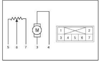
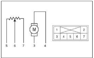
Component Location

Description and Operation
Description
1. Heater unit includes mode control actuator and temperature control actuator.
2. Temperature control actuator is located at the heater unit. It regulates the temperature by the procedure as follows. Signal from control unit adjusts position of temperature door by operating temperature switch and then temperature will be regulated by the hot/cold air ratio decided by position of temperature door.
Repair procedures
Inspection
1. Ignition "OFF".
2. Disconnect the connector of temperature control actuator.
3. Verify that the temperature control actuator operates to the hot position when connecting 12V to the terminal 3 and grounding terminal 4.
Verify that the temperature control actuator operates to the cool position when connecting in the reverse.
[Drive]
- -
- -
- Hot position
- Cool position
- Sensor ground
- Feedback signal
- 5V (Vcc)
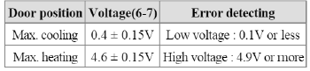
4. Check the voltage between terminals 5 and 6 (Drive).
Specification
![[Passenger]](images/books/1921/23/index%20128.png)
[Passenger]
- -
- -
- Cool position
- Hot position
- 5V (Vcc)
- Feedback signal
- Sensor ground
5. Check the voltage between terminals 6 and 7 (Passenger).
Specification
It will feedback current position of actuator to controls.
6. If the measured voltage is not specification, substitute with a known-good temperature control actuator and check for proper operation.
7. If the problem is collected, replace the temperature control actuator.
Replacement
1. Disconnect the negative (-) battery terminal.
2. Remove the left extension cover (A).

3. Remove the left shower duct (A).

4. Disconnect the temperature control actuator connector (A).
5. Loosen the mounting screw and then remove the temperature control actuator (B).

6. Remove the right extension cover (A).

7. Remove the main crash pad.
(Refer to BD group - "Crash Pad")
8. Remove the right shower duct (A).

9. Disconnect the temperature control actuator connector (A).
10. Loosen the mounting screw and then remove the temperature control actuator (B).

11. Installation is the reverse order of removal.
READ NEXT:
 Mode Control Actuator
Components and
Components Location
Component Location
Description and Operation
Description
The mode control actuator is located at the heater unit.
It adjusts position of mode d
Blower Unit | Blower Motor
Components and Components Location
Component Location
Components
Intake case (LH)
Intake case (RH)
Blower motor
Intake door
Intake actuator
Mofet [Aut
SEE MORE:
Engine Oil
Repair procedures
Oil And Filter Replacement
CAUTION
Prolonged and repeated contact with mineral oil will result in the
removal of natural fats from the skin, leading to
dryness, irritation and dermatitis. In addition, used engine oil contains
potentially harmful contaminants which
m
Schematic Diagrams, Description and Operation
Schematic Diagrams
System Block Diagram
Component Parts And Function Outline
* ETS : Electronic Throttle System
Description and Operation
Cruise Control
The cruise control system is engaged by the cruise "ON/OFF" main switch
located on right of steering wheel
colum
Content
- Home
- Kia Sportage - Fifth generation (NQ5) - (2022-2025) - Owner's Manual
- Kia Sportage - Second generation (JEKM) (2005-2015) - Body Workshop Manual
- Kia Sportage Third generation (SL) - (2011-2016) - Service and Repair Manual
- Sitemap
- Top articles
