Kia Sportage: Mode Control Actuator
Components and Components Location
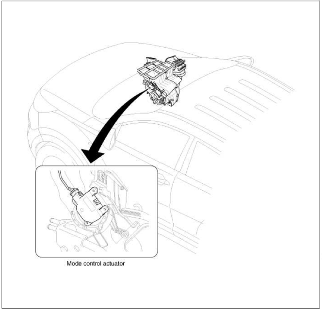
Component Location
Description and Operation
Description
The mode control actuator is located at the heater unit.
It adjusts position of mode door by operating mode control actuator based on signal of А/С control unit. Pressing mode select switch makes the mode control actuator shift in order of vent → B/L → floor → mix.
Repair procedures
Inspection
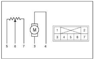
1. Ignition "OFF".
2. Disconnect the connector of mode control actuator.
3. Verify that the mode control actuator operates to the defrost mode when connecting 12V to the terminal 3 and grounding terminal 4.
4. Verify that the mode control actuator operates to the vent mode when connecting in the reverse.
- -
- -
- Defrost mode
- Vent mode
- Sensor ground
- Feedback signal
- 5V (Vcc)
5. Check the voltage between terminals 5 and 6.

It will feedback current position of actuator to controls.
6. If the measured voltage is not specification, substitute with a known-good mode control actuator and check for proper operation.
7. If the problem is corrected, replace the mode control actuator.
Replacement
1. Disconnect the negative (-) battery terminal.
2. Remove the crash pad left side cover (A).

3. Remove the left extension cover (A).

4. Remove the crash pad lower cover (A).

5. Disconnect the diagnosis connector (A).

6. Remove the reinforcing panel (A).

7. Remove the left shower duct (A).

8. Remove the BCM.
(Refer to BE group - "BCM")
9. Disconnect the mode control actuator connector (A).
10. Loosen the mounting screw and then remove the mode control actuator (B).

11. Installation is the reverse order of removal.
READ NEXT:
 Blower Unit | Blower Motor
Components and Components Location
Component Location
Components
Intake case (LH)
Intake case (RH)
Blower motor
Intake door
Intake actuator
Mofet [Aut
SEE MORE:
Components and ComponentsLocation | Removal - Repair procedures
Components (1)
[Hand Type] / [Foot Type]
Parking brake pedal assembly
Front parking brake cable (Foot type only)
Equalizer assembly
Rear parking brake cable
Parking brake lever assembly
Components (2)
[2WD]
Backing plate
Brake shoe
Sh
Power sunshade
Panoramic sunroof (if equipped)
If your vehicle is equipped with a sunroof,
you can slide or tilt your sunroof
with the sunroof switch located on the
overhead console.
The sunroof can only be operated when
the ignition switch or ENGINE START/
STOP button is in the ON or START position.
Content
- Home
- Kia Sportage - Fifth generation (NQ5) - (2022-2025) - Owner's Manual
- Kia Sportage - Second generation (JEKM) (2005-2015) - Body Workshop Manual
- Kia Sportage Third generation (SL) - (2011-2016) - Service and Repair Manual
- Sitemap
- Top articles
