Kia Sportage: Specifications, Components and Components Location | Audio Unit
Specifications
Specifications
Audio

Speaker

Components and Components Location
Component Location
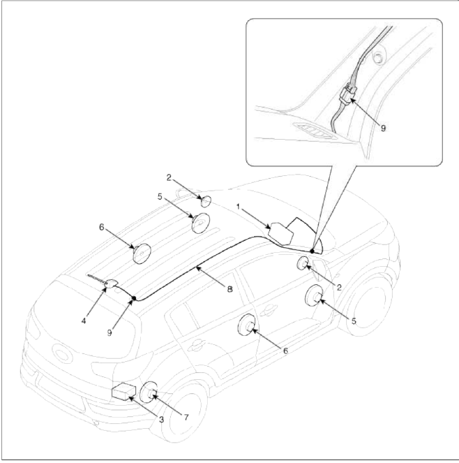
- Audio unit
- Tweeter speaker
- External amplifier
- Roof antenna (Radio)
- Front door speaker
- Rear door speaker
- Sub woofer speaker
- Antenna feeder cable
- Antenna cable connector
Audio Unit
Components and Components Location
Components
[RADIO/CD/MP3 (PA710/PA710S) ]

Connector A
- Speaker RL (+)
- Speaker FL (+)
- Speaker FR (+)
- Speaker RR (+)
- SPDIF GND
- SPDIF DN
- IGN
- Illumination (+)
- DETENT
- Speaker RL (-)
- Speaker FL (-)
- Speaker FR (-)
- Speaker RR (-)
- Remote AMP
- SPDIF DP
- E.AMP MUTE
- Illumination (-)
- Remote Antenna
Connector Ð’
- CAN-H
- TEL MUTE
- TEMP
- Steering remote
- -
- USB D (+)
- USB/iPod VDD
- AUX Input R
- AUX GND
- Mic (+)
- ACC
- Battery (+)
- CAN-L
- -
- -
- Vehicle speed
- Remote GND
- USB D (-)
- USB/iPod GND
- AUX Detect
- AUX Input L
- Mic (-)
- -
- Power GND
[RADIO/CD/MP3 (BA900/BA950) - External Amplifier]

Connector A
- Speaker RL (+)
- Speaker FL (+)
- Speaker FR (+)
- Speaker RR (+)
- -
- -
- Ignition
- Illumination (+)
- -
- Speaker RL (-)
- Speaker FL (-)
- Speaker FR (-)
- Speaker RR (-)
- P position
- -
- -
- Illumination (-)
- Remote antenna
Connector Ð’
- CAN-H
- -
- -
- Steering remote
- -
- Camera_V_IN
- Camera B+
- AUX_R_IN
- AUX_REF
- MIC+(BT)
- ACC
- B/UP
- CAN-L
- -
- Auto light
- Speed IN
- Remote GND
- Camera V_GND
- Camera REQ
- AUX_Detect
- AUX_L_IN
- MIC-(BT)
- Camera_P_GND
- Power GND
[RADIO/CD/MP3 (BA900/BA950) - Internal Amplifier]

Connector A
- -
- -
- -
- -
- SPDIF GND
- SPDIF DN
- Ignition
- Illumination (+)
- -
- -
- -
- -
- -
- P position
- SPDIF DP
- -
- Illumination (-)
- Remote antenna
Connector Ð’
- CAN-H
- -
- -
- Steering remote
- -
- Camera_V_IN
- Camera B+
- AUX_R_IN
- AUX_REF
- MIC+(BT)
- ACC
- B/UP
- CAN-L
- -
- Auto light
- Speed IN
- Remote GND
- Camera V_GND
- Camera REQ
- AUX_Detect
- AUX_L_IN
- MIC-(BT)
- Camera_P_GND
- Power GND
[External Amplifier]
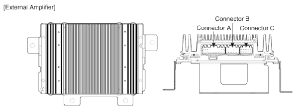
 Connector A
- B (+)
- B (+)
- B (+)
- -
- CAN (+)
- CAN (-)
- ACC
- -
- -
- -
- Navigation (+)
- Sub woofer 2 (+)
- Sub woofer 1 (+)
- GND
- GND
- GND
- -
- SPDIF (+)
- SPDIF (-)
- -
- -
- -
- -
- Navigation (-)
- Sub woofer 2 (-)
- Sub woofer 1 (-)
 Connector B
- -
- -
- -
- -
- -
- -
- -
- -
- -
- -
- -
- -
- -
- -
- -
- -
 Connector C
- Rear Door Right (+)
- Rear Door Left (+)
- Front Tweeter Right (+)
- Front Tweeter Left (+)
- Front Door Right (+)
- Front Door Left (+)
- Rear Door Right (-)
- Rear Door Left (-)
- Front Tweeter Right (-)
- Front Tweeter Left (-)
- Front Door Right (-)
- Front Door Left (-)
[Roof Antenna (Radio) ]
![[Roof Antenna (Radio+GPS) ]](images/books/1921/7/index%208.png)
[Roof Antenna (Radio+GPS) ]

Repair procedures
Removal
1. Disconnect the negative (-) battery terminal.
2. Remove the crash pad passenger's garnish (A).
(Refer to BD group - "Crash pad")

3. Disconnect the connectors and remove the cluster fascia panel (A).
(Refer to BD group - "Crash pad")

4. Remove the center fascia panel (A) after loosening the mounting screw (2EA).

5. Disconnect the connector (A) installed on the center fascia panel.

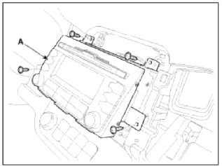
6. Remove the audio assembly (A) after loosening the mounting screw (4EA).
7. Disconnect the audio connectors and cable (A), then remove the audio unit completely.

NOTE
Lift the connector locking clip to the arrow direction, disconnect the connector.
When assembling, install the connector and connector locking clip.
CAUTION
- If CD does not eject, don't try to remove it.
- The player may be damaged.
- Therefore, contact a service shop for repairs
Installation
1. Connect the audio unit connectors and cable.
2. Install the audio unit.
3. Install the center fascia panel.
4. Install the cluster fascia panel.
5. Install the crash pad passenger's garnish.
6. Connect the negative (-) battery terminal.
NOTE
- Make sure the connector are connected in properly.
- Check the audio system.
Disassembly
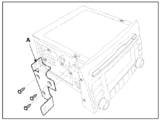
1. Loosen the screw (Left 3EA. Right 3EA) and remove the audio head unit mounting bracket (A).
2. When separate the CD rom drive, if necessary, remove the top cover (A) after loosening the screws (4EA).

3. After loosening the screws, remove the CD rom drive (B).

NOTE
Take care not to damage the cable connectors (A) when removing drive.
READ NEXT:
 Speakers
Repair procedures
Inspection
1. Troubleshooting for Speaker
Basic inspection of speaker
Inspect the sound from speaker after verifying that the speaker mounting
screws are removed
Antenna | Audio Remote Control
Repair procedures
Inspection
Antenna Cable
1. Remove the antenna jack from the audio unit and antenna.
2. Check for continuity between the center poles of antenna cable.
3. Check for cont
SEE MORE:
Rear Seat
Components and Components
Location
Components
Headrest
Headrest guide
Tether anchor garnish
Upper bezel
Rear seat back pad
Latch cover
Rear seat back cover
Armrest board
Rear armrest
Rear seat back frame
Rear seat cushion cover
Rear seat cushion warmer
Rear seat
High Pressure Fuel Pump
Repair procedures
Removal
WARNING
In case of removing the high pressure fuel pump, high pressure fuel pipe,
delivery pipe, and injector, there may be
injury caused by leakage of the high pressure fuel. So don't do any repair work
right after engine stops.
1. Turn the ignition switch OFF and
Content
- Home
- Kia Sportage - Fifth generation (NQ5) - (2022-2026) - Owner's Manual
- Kia Sportage - Second generation (JEKM) (2005-2015) - Body Workshop Manual
- Kia Sportage Third generation (SL) - (2011-2016) - Service and Repair Manual
- Sitemap
- Top articles
