Kia Sportage: EBD (Electronic Brake-force Distribution) | ESC Control Module
Description and Operation
Operation
The EBD system (Electronic Brake force Distribution) as a sub-system of the ABS system is to control the maximum braking effectiveness by the rear wheels.
It further utilizes the efficiency of highly developed ABS equipment by controlling the slip of the rear wheels in the partial braking range.
The brake force is moved even closer to the optimum and controlled electronically, thus dispensing with the need for the proportioning valve.
The proportioning valve, because of a mechanical device, has limitations to achieve an ideal brake force distribution to the rear wheels as well as to carry out the flexible brake force distribution proportioning to the vehicle load or weight increasing. And in the event of malfunctioning, driver cannot notice whether it fails or not.
EBD controlled by the ABS Control Module, calculates the slip ratio of each wheel at all times and controls the brake pressure of the rear wheels not to exceed that of the front wheels.
If the EBD fails, the EBD warning lamp (Parking brake lamp) lights up.
Advantages
- Function improvement of the base-brake system.
- Compensation for the different friction coefficients.
- Elimination of the proportioning valve.
- Failure recognition by the warning lamp.
Comparison between Proportioning Valve and EBD

ESC Control Module
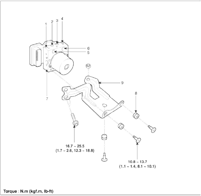
Components and Components Location
Components

- Front - left tube
- Rear - right tube
- Rear - left tube
- Front - right tube
- MC2
- MC1
- ESC control module (HECU)
- Damper
- Bracket
Repair procedures
Removal
1. Turn the ignition switch OFF.
2. Disconnect the brake tubes from the HECU by unlocking the nuts counterclockwise with a spanner
Tightening torque:
12.7 ~ 16.7N.m (1.3 ~ 1.7kgf.m, 9.4 ~ 12.3lb-ft)
16.7 ~ 22.6N.m (1.7 ~ 2.3kgf.m, 12.3 ~ 16.6lb-ft)
3. Pull up the lock of the ESC control unit connector, then disconnect the connector.

4. Loosen the ESC HECU bracket bolts (A) and nut (B), then remove HECU and bracket.
Tightening torque: 16.7 ~ 25.5N.m (1.7 ~ 2.6kgf.m, 12.3 ~ 18.8lb-ft)

CAUTION
1. Never attempt to disassemble the HECU.
2. The HECU must be transported and stored in.
3. Never shock to the HECU.
5. Remove the 3 bolts, then remove the bracket from HECU.
Tightening torque: 10.8 ~ 13.7N.m (1.1 ~ 1.4kgf.m, 8.0 ~ l0.1lb-ft)
Installation
1. Installation is the reverse of removal.
2. Tighten the HECU mounting bolts and nuts to the specified torque.
3. After installation, bleed the brake system. (Refer to ABS bleeding).
Variant coding
2WD and 4WD vehicle are sharing the HECU each other. To apply appropriate vehicle, HECU needs to variant coding process.
Variant coding process is necessary when :
- HECU is replaced.
- C l702 DTC (variant coding error) code is detected.
READ NEXT:
 Front Wheel Speed Sensor | Rear Wheel Speed Sensor
Components and Components Location
Components
Front wheel speed sensor connector
Front wheel speed sensor
Repair procedures
Removal
1. Remove the front wheel speed sensor mou
SEE MORE:
 Opening the liftgate
Power liftgate(if equipped )
Power liftgate open/close button
Power liftgate handle switch
Power liftgate close button
Power liftgate open/close button
NOTICE
If ignition switch or ENGINE START/
STOP button is ON position, the power
liftgate can operate wh
 Intake Actuator
Components and Components
Location
Component Location
Description and Operation
Description
1. The intake actuator is located at the blower unit.
2. It regulates the intake door by signal from control unit.
3. Pressing the intake selection switch will shift between recirculation a
Content
- Home
- Kia Sportage - Fifth generation (NQ5) - (2022-2025) - Owner's Manual
- Kia Sportage - Second generation (JEKM) (2005-2015) - Body Workshop Manual
- Kia Sportage Third generation (SL) - (2011-2016) - Service and Repair Manual
- Sitemap
- Top articles