Kia Sportage: Shift Lever
Components and Components Location
Components
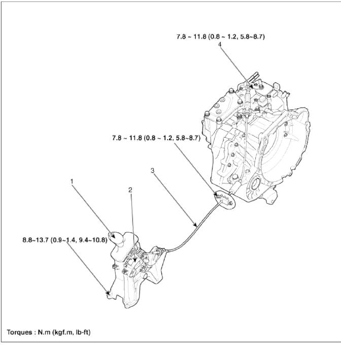
- Shift lever knob & boots assembly
- Shift lever assembly
- Control cable assembly
- Manual control lever (T/M side)
Repair procedures
Removal
Shift Lever Assembly Replacement
1. Remove the center console assembly. (Refer to "Interior (console)" in BD group.)
2. Disconnect sports mode connector (A).

3. Take off the clip (A) and then remove the shift cable (B).
4. Remove the shift lever assembly (D) by removing the bolts (C-4ea).
Tightening torque: 8.8 ~ 13.7 N.m (0.9 ~ 1.4 kgf.m, 6.5 ~ 10.1 lb-ft)

5. Installation is the reverse of removal.
NOTE
Make sure vehicle does not roll before setting room side shift lever and T/M side manual control lever to "N" position.
Control Cable Replacement
1. Remove the center console assembly. (Refer to "Interior (console)" in BD group.)
2. Take off the clip (A) and then remove the control cable (B).

3. Remove the control cable assembly in the vehicle after removing the nuts (B) and the retainer (A).
Tightening torque: 7.8 ~ 11.8 N.m (0.8 ~ 1.2 kgf.m, 5.8 ~ 8.7 lb-ft)

4. Remove the nut (C).
5. Remove the cable (B) from the bracket (A) at transaxle assembly side (Refer to "Automatic Transaxle" in this group).

6. Remove the control cable inside of cab.
Inspection
1. Check the damage and operation of the control cable.
2. Check the damage of the boot.
3. Check the damage and corrosion of the bushing.
4. Check the damage or weakening of the spring.
Installation
1. Installation is the reverse of removal.
NOTE
Make sure vehicle does not roll before setting room side shift lever and T/M side manual control lever to "N" position.
Adjustment
Adjusting method for T/M control cable
1. Make sure vehicle does not roll before setting room side shift lever and T/M side manual control lever to "N" position.
2. Connect room side shift lever and control cable (A).

3. Push cable to "F" direction shown to eliminate FREE PLAY.
4. Tighten adjusting nut (A).
Tightening torque: 7.8 ~ 11.8 N.m (0.8 ~ 1.2 kgf.m, 5.8 ~ 8.7 lb-ft)

5. After adjusting, check to be sure that this part operates as designed at each range of T/M side corresponding to each position of room lever.
READ NEXT:
 General Information
Specifications
Specifications
Tightening Torque
Special Service Tools
Special Tools
Troubleshooting
Troubleshooting
SEE MORE:
Rear Upper Arm | Rear Lower Arm
Repair procedures
Replacement
1. Remove the rear wheel & tire.
Tightening torque: 88.3 ~ 107.9N.m (9.0 ~ 11.0kgf.m, 65.1 ~ 79.6lb-ft)
CAUTION
Be careful not to damage to the hub bolts when removing the front wheel & tire (A).
2. Loosen the bolt & nut and then remove the re
Waterproof and rustproof
Sealing
To waterproof and rustproof the vehicle, apply sealer on assembled area of
the body panel and on any areas in
contact with the body, such as doors (inner/outer), hood (inner/outer), and tail
gate (inner/outer).
Body (Floor)
View
Section
Door
View
Section
Hood
Se
Content
- Home
- Kia Sportage - Fifth generation (NQ5) - (2022-2025) - Owner's Manual
- Kia Sportage - Second generation (JEKM) (2005-2015) - Body Workshop Manual
- Kia Sportage Third generation (SL) - (2011-2016) - Service and Repair Manual
- Sitemap
- Top articles
