Kia Sportage: Repair procedures | Canister
Inspection
[System Inspection]
1. Disconnect the vapor hose from the intake manifold and connect a vacuum pump to the nipple on the intake manifold.
- At Cold Engine [Engine Coolant Temperature < 60ºC(140ºF) ]

2. Check the following points with applied vacuum at the purge control solenoid valve (PCSV).
- At Warmed Engine [Engine Coolant Temperature > 80ºC(176ºF) ]
![[PCSV Inspection]](images/books/1921/16/index%20143.png)
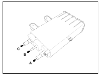
[PCSV Inspection]
1. Turn ignition switch OFF and disconnect the negative (-) battery cable.
2. Disconnect the PCSV connector (A).
3. Disconnect the vapor hose (B) which is connected to the intake manifold from the PCSV.

4. After connecting a vacuum pump to the nipple, apply vacuum.
5. With the PCSV control line grounded, check the valve operation with battery voltage applied to the PCSV (Open) and removed (Closed).

6. Measure the coil resistance of the PCSV.
Specifications: 19.0 ~ 22.0Ω [20ºC (68ºF) ]
[EVAP Leakage Test]
1. Select "Evap. Leakage Test".

2. Proceed with the test according to the screen introductions.

Canister
Repair procedures
Removal
1. Remove the fuel tank. (Refer to "Fuel tank" in FL group.)
2. Disconnect the vapor tube quick-connector (B) and the ventilation hose (A).
3. Remove the canister in the direction of an arrow after removing the installation screws (C).

Inspection
1. Check for the following items visually.
- Cracks or leakage of the canister.
- Loose connection, distortion, or damage of the vapor hose/tube.
- Canister ↔ Atmosphere
- Canister ↔ Intake Manifold
- Canister ↔ Fuel Tank
Installation
Installation is the reverse of removal.
READ NEXT:
 Fuel Filler Cap | Fuel Tank Air Filter
Description and Operation
Description
A ratchet tightening device on the threaded fuel filler cap reduces the chances of incorrect installation, which seals the fuel filler. After the gasket
SEE MORE:
Drive mode integrated control system
Drive mode
The drive mode may be selected according
to the driver's preference or road
condition.
Type A
Type B
Type C
The Drive mode is activated by turning
the knob.
NOTICE
If there is a problem with the instrument
cluster, the drive mode will be in NORMAL
mode and may
Description and Operation | Repair procedures
Description
The starting system includes the battery, starter, solenoid switch, ignition switch, inhibitor switch (A/T), clutch pedal switch (M/T), ignition lock switch, connection wires and the battery cable.
When the ignition key is turned to the start position, current flows and energiz
Content
- Home
- Kia Sportage - Fifth generation (NQ5) - (2022-2026) - Owner's Manual
- Kia Sportage - Second generation (JEKM) (2005-2015) - Body Workshop Manual
- Kia Sportage Third generation (SL) - (2011-2016) - Service and Repair Manual
- Sitemap
- Top articles
