Kia Sportage: Power Mosfet | Blower Resistor | Climate Control Air Filter
Repair procedures
Inspection
1. Ignition "ON".
2. Manually operate the control switch and measure the voltage of blower motor.
Đ—. Select the control switch to raise voltage until high speed.

Specification

*AUTO COOLING : Auto speed (4.5V~B+) *AUTO HEATING : Auto speed (4.5V~11.0V)
4. If the measured voltage is not specification, substitute with a known-good power mosfet and check for proper operation.
5. If the problem is collected, replace the power mosfet.
Replacement
1. Disconnect the negative (-) battery terminal.
2. Disconnect the power mosfet connector (A) and then remove the power mosfet (B) after loosening the mounting screws.

3. Installation is the reverse order of removal.
Blower Resistor
Repair procedures
Inspection
1. Measure terminal-to-terminal resistance of the blower resistor.
2. Measured resistance is not within specification, the blower resistor must be replaced. (After removing the resistor.
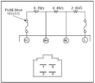
- ML
- MH
- LO
- HI
Replacement
1. Disconnect the negative (-) battery terminal.
2. Disconnect the blower resistor connector (A) and then remove the blower resistor (B) after loosening the mounting screws.

3. Installation is the reverse order of removal.
Climate Control Air Filter
Description and Operation
Description
This has particle filter which eliminates foreign materials and odor. The particle filter includes odor filter as well as conventional dust filter to ensure comfortable interior environment.
Repair procedures
Replacement
1. Disconnect the damper (B) and glove box lift (C) from the glove box (A).

2. Remove the filter cover with pushing the knob.

3. Replace the air filter (B), install it after making sure of the direction of air filter.

NOTE
In case of driving in an air-polluted area or rugged terrain, check and replace the aft filter as frequently as possible.
4. Installation is the reverse order of removal.
READ NEXT:
 Intake Actuator
Components and Components
Location
Component Location
Description and Operation
Description
1. The intake actuator is located at the blower unit.
2. It regulates the intake door by sig
SEE MORE:
Pressure Sensor
Description and Operation
Description
The 4WD ECU makes a Motor Pump (Actuator) turn round for generating an oil
pressure. And then it presses a multiple
disk clutch and transfers the generated torque into rear wheels. Its torque
value varies according to a pressure status.
Schematic
CVVT Oil Temperature Sensor (OTS)
Description and
Operation
Description
Continuous Variable Valve Timing (CVVT) system advances or retards the valve
tuning of the intake and exhaust
valve in accordance with the ECM control signal which is calculated by the
engine speed and load.
By controlling CWT , the valve over-l
Content
- Home
- Kia Sportage - Fifth generation (NQ5) - (2022-2024) - Owner's Manual
- Kia Sportage - Second generation (JEKM) (2005-2015) - Body Workshop Manual
- Kia Sportage Third generation (SL) - (2011-2016) - Service and Repair Manual
- Sitemap
- Top articles
