Kia Sportage: Intake Actuator
Components and Components Location
Component Location

Description and Operation
Description
1. The intake actuator is located at the blower unit.
2. It regulates the intake door by signal from control unit.
3. Pressing the intake selection switch will shift between recirculation and fresh air modes.
Repair procedures
Inspection
1. Ignition "OFF"
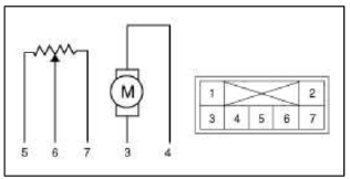
2. Disconnect the intake actuator connector.
3. Verify that the actuator operates to the recirculation position when connecting 12V to the terminal 3 and grounding terminal 4.
4. Verify that the intake actuator operates to the fresh position when connecting in the reverse.
- -
- -
- Fresh
- Recirculation
- 5V (Vcc)
- Feedback Signal
- Sensor Ground
5. Check the voltage between terminals 6 and 7.

6. If the intake actuator is not operated well, substitute with a known-good intake actuator and check for proper operation.
7. If the problem is corrected, replace the intake actuator.
Replacement
1. Disconnect the negative (-) battery terminal.
2. Remove the right extension cover (A).

3. Remove the crash pad.
(Refer to BD group - "Crash Pad")
4. Remove the right shower duct (A).

5. Disconnect the Intake actuator connector (A).
6. Loosen the mounting screw and then remove the intake actuator (B).

7. Installation is the reverse order of removal.
READ NEXT:
 Heater & A/C Control Unit (Manual, Full Automatic)
Components and Components Location
Components
Connector Pin Function
Repair procedures
Replacement
1. Disconnect the negative (-) battery terminal.
2. Using the screwdriver, remove t
SEE MORE:
Description and Operation
OBD-II review
1. Overview
The California Air Resources Board (CARB) began regulation of On Board
Diagnostics (OBD) for vehicles sold in
California beginning with the 1988 model year. The first phase, OBD-L required
monitoring of the fuel metering
system, Exhaust Gas Recirculation (EGR)
Components and Components Location | Description and Operation
Components
HECU module
Front wheel speed sensor
Rear wheel speed sensor
Yaw rate & Lateral & Longitudinal G sensor
Steering angle sensor
ABS Warning lamp
Parking brake EBD warning lamp
ESC OFF lamp
ESC Function/Warning lamp
DBC war
Content
- Home
- Kia Sportage - Fifth generation (NQ5) - (2022-2026) - Owner's Manual
- Kia Sportage - Second generation (JEKM) (2005-2015) - Body Workshop Manual
- Kia Sportage Third generation (SL) - (2011-2016) - Service and Repair Manual
- Sitemap
- Top articles
