Kia Sportage: Heater & A/C Control Unit (Manual, Full Automatic)
Components and Components Location
Components

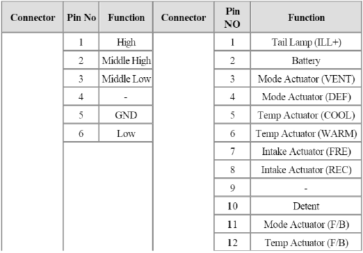
Connector Pin Function

Repair procedures
Replacement
1. Disconnect the negative (-) battery terminal.
2. Using the screwdriver, remove the cluster facia panel (A).

3. Using the screwdriver, remove the crash pad garnish (A).

4. Using the screwdriver, remove the screws and center facia panel (A).

5. Disconnect the center facia connectors (A).

6. Loosen the control panel mounting screws and then remove the control panel (A).

7. Disconnect the connectors and then remove the control panel (B).

8. Installation is the reverse order of removal.
Heater & A/C Control Unit (Full Automatic)
Components and Components Location
Component

Connector Pin Function

Repair procedures
Self Diagnosis
1. Self-diagnosis process

2. How to read self-diagnostic code
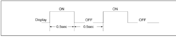
After the display panel flickers three tunes every 0.5 second, the corresponding fault code flickers on the setup temperature display panel every 0.5 second and will show two figures. Codes are displayed in numerical format.
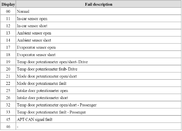
Fault Code

3. Fault code display
- Continuance operation : DTC code is one.
- Continuance operation : DTC code of two or more.
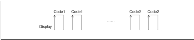
- STEP operation

4. If fault codes are displayed during the check. Inspect specific malfunctions causes by fault codes.
5. Fail safe
- In-car temperature sensor: Control with the value of 23ºC (73.4ºF)
- Ambient temperature sensor: Control with the value of 20ºC (67ºF)
- Evaporator temperature sensor: Control with the value of -2ºC (28.4ºF)
- Water temperature sensor: Control with the value of 85ºC (185ºF)
- Temperature control actuator (Air mix potentiometer): If temperature setting 17ºC-24.5ºC, fix at maximum cooling position.
If temperature setting 25ºC-32ºC, fix at maximum heating position.
- Mode control actuator (Direction potentiometer): Fix vent position, while selecting vent mode.
Fix defrost position, while selecting all except vent mode.
- Intake control actuator: Fix fresh position, while selecting fresh mode.
Fix recirculation position, while selecting recirculation mode.
Replacement
1. Disconnect the negative (-) battery terminal.
2. Using the screwdriver, remove the cluster facia panel (A).

3. Using the screwdriver, remove the crash pad garnish (A).

4. Using the screwdriver, remove the center facia panel (A).

5. Disconnect the center facia connectors (A).

6. Loosen the control panel mounting screws and then remove the control panel (A).

7. Disconnect the connectors and then remove the control panel (B).

8. Installation is the reverse order of removal.
READ NEXT:
SEE MORE:
 Components and Components Location | Front Seat Belt
Components
Front seat belt
Height adjuster
Rear seat belt
Rear seat belt [Center]
Rear seat belt buckle
Front Seat Belt
Repair procedures
Replacement
Front Seat Belt Replacement
CAUTION
When installing the belt, make sure not to damaged the pre
Ignition System
Description and Operation
Description
Ignition timing is controlled by the electronic control ignition timing
system. The standard reference ignition timing
data for the engine operating conditions are preprogrammed in the memory of the
ECM (Engine Control Module).
The engine operati
Content
- Home
- Kia Sportage - Fifth generation (NQ5) - (2022-2026) - Owner's Manual
- Kia Sportage - Second generation (JEKM) (2005-2015) - Body Workshop Manual
- Kia Sportage Third generation (SL) - (2011-2016) - Service and Repair Manual
- Sitemap
- Top articles
