Kia Sportage: Front Lower Arm | Front Stabilizer Bar
Repair procedures
Replacement
1. Remove the front wheel & tire.
Tightening torque: 88.3 ~ 07.9N.m (9.0 ~ 11.0kgf.m, 65.1 ~ 79.6lb-ft)

CAUTION
Be careful not to damage to the hub bolts when removing the front wheel & tire (A).
2. Loosen the bolt & nut and then remove the lower arm (A).
Tightening torque: 98.1 ~ 117.7N.m (10.0 ~ 12.0kgf.m, 72.3 ~ 86.8lb-ft)

3. Remove the front lower arm (A) and then loosen the bolts & nuts.
Tightening torque:
Front
117.7 ~ 137.3N.m (12.0 ~ 14.0kgf.m, 86.8 ~ 101.3lb-ft)
Rear
137.3 ~ 156.9N.m (14.0 ~ 16.0kgf.m, 101.3 ~ 115.7lb-ft)

4. Installation is the reverse of removal.
Inspection
1. Check the bushing for wear and deterioration.
2. Check the lower arm for bending or breakage.
3. Check the lower arm for deformation.
4. Check the all bolts and nuts.
Front Stabilizer Bar
Components and Components Location
Components
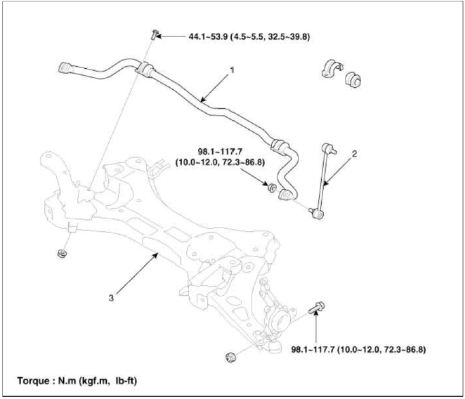
- Stabilizer Bar
- Stabilizer link
- Sub frame
Repair procedures
Replacement
1. Remove the front wheel & tire.
Tightening torque: 88.3 ~ 107.9N.m (9.0 ~ 11.0kgf.m, 65.1 ~ 79.6lb-ft)

CAUTION
Be careful not to damage to the hub bolts when removing the front wheel & tire (A).
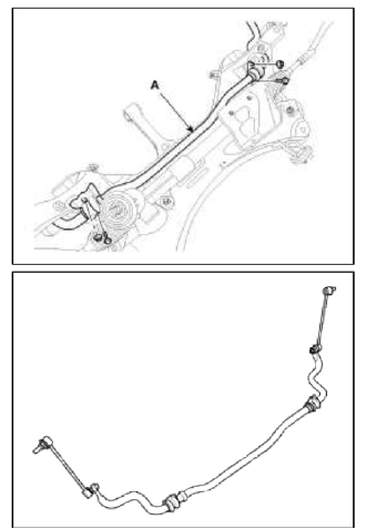
2. Disconnect the stabilizer link (B) from the front strut assembly (A) after loosening the nut.
Tightening torque: 98.1 ~ 117.7N.m (10.0 ~ 12.0kgf.m, 72.3 ~ 86.8lb-ft)

3. Remove the split pin and castle nut and then disconnect the tie-rod end (A) from the front knuckle.
Tightening torque: 34.3 ~ 44.1N.m (3.5 ~ 4.5kgf.m, 25.3 ~ 32.5lb-ft)

4. Loosen the bolt & nut and then remove the lower arm (A).
Tightening torque: 98.1 ~ 117.7N.m (10.0 ~ 12.0kgf.m, 72.3 ~ 86.8lb-ft)

5. Remove the dust cover.
6. Loosen the bolt (A) and then disconnect the universal joint assembly from the pinion of the steering gear box.
Tightening torque: 29.4 ~ 34.3N.m (3.0 ~ 3.5kgf.m, 21.7 ~ 25.3lb-ft)

CAUTION
- Keep the neutral-range to prevent the damage of the clock spring inner cable when you handle the steering wheel.
- Do not use the bolt again.
7. Remove the under cover (A).

8. Loosen the bolt (A) & nut (B) and then remove the roll rod stopper.
Tightening torque: 107.9 ~ 127.5N.m (11.0 ~ 13.0kgf.m, 79.6 ~ 94.0lb-ft)

9. Disconnect the muffler rubber hanger (A).

10. Loosen the bolts & nuts and then remove the sub frame.
Tightening torque: 176.5 ~ 196.1N.m (18.0 ~ 20.0kgf.m, 130.2 ~ 144.7lb-ft)

11. Loosen the bolt and then remove the stabilizer (A) from the sub frame.
Tightening torque: 44.1 ~ 53.9N.m (4.5 ~ 5.5kgf.m, 32.5 ~ 39.8lb-ft)
12. Installation is the reverse of removal.
Inspection
1. Check the bushing for wear and deterioration.
2. Check the front stabilizer bar for deformation.
3. Check the front stabilizer link ball joint for damage
READ NEXT:
 Front Cross Member
Repair procedures
Replacement
1. Remove the front wheel & tire.
Tightening torque:
88.3 ~ 107.9N.m (9.0 ~ 11.0kgf.m, 65.1 ~ 79.6lb-ft)
CAUTION
Be careful not to damage to the hub bol
SEE MORE:
General Information
Specifications
Specifications
Ignition System
Starting System
Charging System
CAUTION
COLD CRANKING AMPERAGE is the amperage a battery can deliver for 30
seconds and maintain a
terminal voltage of 7.2V or greater at a specified temperature.
RESERVE CAPACITY RATING is amou
Starter Relay
Repair procedures
Inspection
1. Remove the fuse box cover.
2. Remove the starter relay (A).
3. Using an ohmmeter, check that there is continuity between each terminal.
4. Apply 12V to terminal 85 and ground to terminal 86.
Check for continuity between terminals 30 and 87.
5. If ther
Content
- Home
- Kia Sportage - Fifth generation (NQ5) - (2022-2026) - Owner's Manual
- Kia Sportage - Second generation (JEKM) (2005-2015) - Body Workshop Manual
- Kia Sportage Third generation (SL) - (2011-2016) - Service and Repair Manual
- Sitemap
- Top articles
