Kia Sportage: Front Bumper | Rear Bumper
Components and Components Location
Components
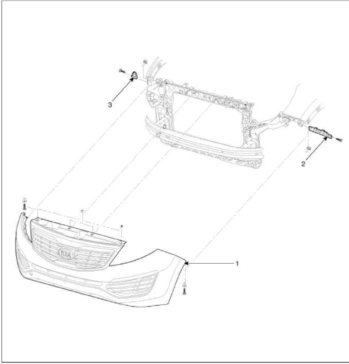
- Front bumper cover
- Front bumper side bracket [LH]
- Front bumper side bracket [RH]
Repair procedures
Replacement
CAUTION
- Put on gloves to protect your hands.
- Use a plastic panel removal tool to remove interior trip pieces to without marring the surface.
- Take care not bend or scratch the cover and other parts.
1. Loosen the radiator upper cover (A) mounting clips and bolts.

2. Remove the under cover (A) mounting clips.

3. After loosening the front bumper side's mounting screw, then disconnect the side's.

4. Disconnect the fog lamp (A), turn signal lamp (B), front sensor (C).
5. Remove the front bumper.
[LH]
![[RH]](images/books/1921/6/index%205.png)
[RH]

6. Installation is the reverse of removal.
NOTE
- Make sure the connector is plugged in properly.
- Replace any damage clips.
Rear Bumper
Components and Components Location
Components
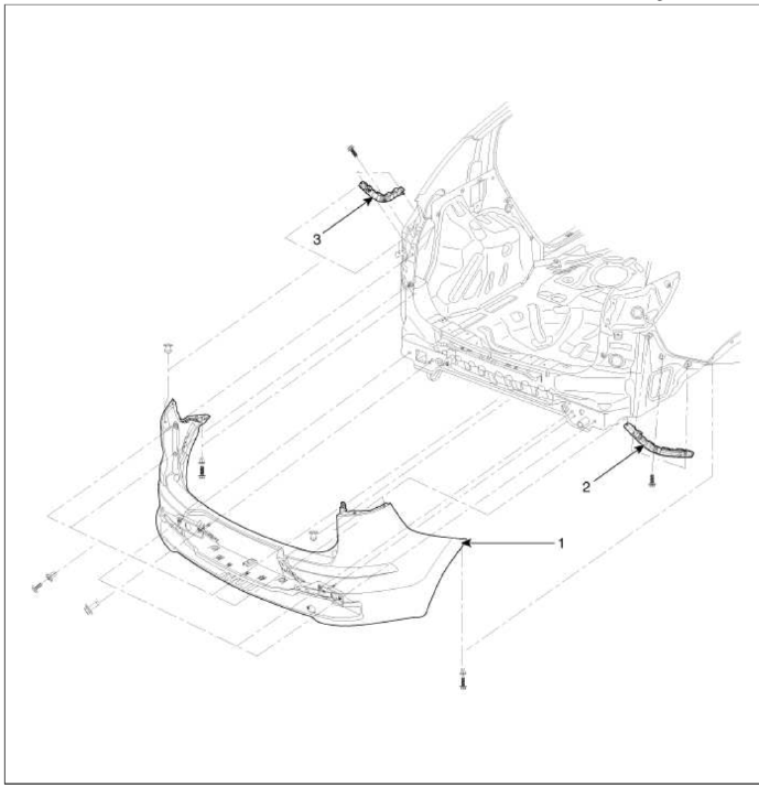
- Front bumper cover
- Front bumper side bracket [RH]
- Front bumper side bracket [LH]
Repair procedures
Replacement
CAUTION
- Put on gloves to protect your hands.
- Use a plastic panel removal tool to remove interior trip pieces to without marring the surface.
- Take care not bend or scratch the cover and other parts.
1. After loosening the mounting screws, then remove the rear combination lamp (A).
2. Push the lock pin, disconnect the connector (B).

3. After loosening the rear bumper side's mounting screws and clip, then disconnect the side's.

4. Loosen the mounting bolts.

5. After loosening the mounting screws and clip, then remove the rear bumper (A).

6. Push the lock pin, disconnect the rear bumper main connector (A).

7. Installation is the reverse of removal.
NOTE
- Make sure the connector is plugged in properly.
- Replace any damage clips.
READ NEXT:
 Front Seat
Components and Components
Location
Components
Headrest
Headrest guide
Front seat back cover
Front seat back heater
Front seat back pad
Front seat back power lumbar
Front seat
SEE MORE:
Warning Control
Warning Control
1. The Warning function offers the following features
Seat Belt Warning
Seat Belt Re minder
Over Speed Warning
Key Reminder Warning
Parking Brake Warning
RKE Key Teaching sound
SMK System Warning
RAPS Warning
Rheostat Detent Warning
2. Buzzer Operation
Cruise Control (CC)
Cruise Control (CC) (if equipped)
Cruise indicator
Set speed
Cruise Control will allow you to drive at
speeds above 20 mph (30 km/h) without
depressing the accelerator pedal.
Cruise Control operation
To set speed
Accelerate to the desired speed,
which must be more than 20 mph
Content
- Home
- Kia Sportage - Fifth generation (NQ5) - (2022-2025) - Owner's Manual
- Kia Sportage - Second generation (JEKM) (2005-2015) - Body Workshop Manual
- Kia Sportage Third generation (SL) - (2011-2016) - Service and Repair Manual
- Sitemap
- Top articles
