Kia Sportage: Description and Operation, Specifications, Troubleshooting, Schematic Diagrams | Components and Components Location
Kia Sportage Third generation (SL) - (2011-2016) - Service and Repair Manual / Emission Control System / General Information / Description and Operation, Specifications, Troubleshooting, Schematic Diagrams | Components and Components Location
Description and Operation
Description
Emissions Control System consists of thee major systems.
- The Crankcase Emission Control System prevents blow-by gas from releasing into the atmosphere. This system recycles gas back into the intake manifold (Closed Crankcase Ventilation Type).
- The Evaporative Emission Control System prevents evaporative gas from releasing into the atmosphere. This system bums gas at appropriate engine operating condition after gathering it in the canister.
- The Exhaust Emission Control System converts the thee pollutants [hydrocarbons (HC), carbon monoxide (CO), and oxides of nitrogen (NOx)] into harmless substances by using the 3-way catalytic converter.
Specifications
Specifications
Purge Control Solenoid Valve (PCSV)
Specification

Fuel Tank Pressure Sensor (FTPS)
Type: Piezo-Resistive Pressure Sensor
Specification

Canister Close Valve (CCV)
Specification

Tightening Torques

Troubleshooting
Troubleshooting

Schematic Diagrams
Schematic Diagram

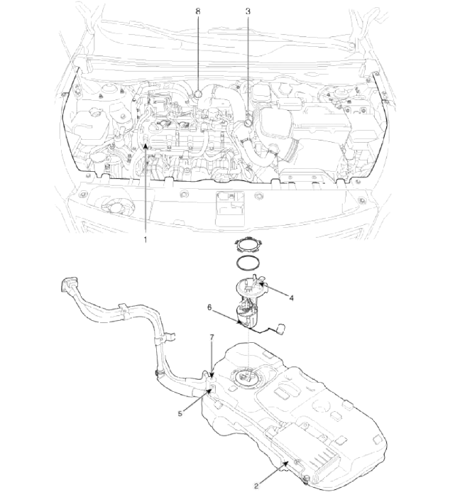
Components and Components Location
Components Location
- PCV valve
- Canister
- Purge control solenoid valve (PCSV)
- Fuel tank pressure sensor (FTPS)
- Canister close valve (CCV)
- Fuel level sensor (FLS)
- Fuel tank air filter
- Catalytic converter (CCC)
1. PCV Valve

2. Canister

3. Purge Control Solenoid Valve (PCSV)

4. Fuel Tank Pressure Sensor (FTPS)

5. Canister Close Valve (CCV)
7. Fuel Tank Air Filter

6. Fuel Level Sensor (FLS)

8. Catalytic converter (CCC)

READ NEXT:
 Schematic Diagrams, Repair procedures | Positive Crankcase Ventilation (PCV) Valve
Schematic Diagrams
Schematic Diagram
Repair procedures
Inspection
1. After disconnecting the vapor hose from the PCV valve, remove the PCV valve.
2. Reconnect the PCV valve to the vapor
SEE MORE:
Side body panel
Front inner pillar assembly
Quarter inner panel assembly
Side outer rear extension assembly
Quarter outer panel assembly
Center outer pillar assembly
Pillar outer panel assembly
Side assembly outer panel
Center floor panel
Front seat cross rear member assembly
Center floo
Coat hook
A Coat hook is next to the rear grab handle.
* This actual feature may differ from the
illustration.
CAUTION
Hanging clothing
Do not hang heavy clothes, since they
may damage the hook.
WARNING
Do not hang other objects such as hangers
or hard objects except clothes. Also,
do not put he
Content
- Home
- Kia Sportage - Fifth generation (NQ5) - (2022-2025) - Owner's Manual
- Kia Sportage - Second generation (JEKM) (2005-2015) - Body Workshop Manual
- Kia Sportage Third generation (SL) - (2011-2016) - Service and Repair Manual
- Sitemap
- Top articles
