Kia Sportage: Components and Components Location, Description and Operation
Kia Sportage Third generation (SL) - (2011-2016) - Service and Repair Manual / Suspension System / Tire Pressure Monitoring System / Components and Components Location, Description and Operation
Components and Components Location
Components Location
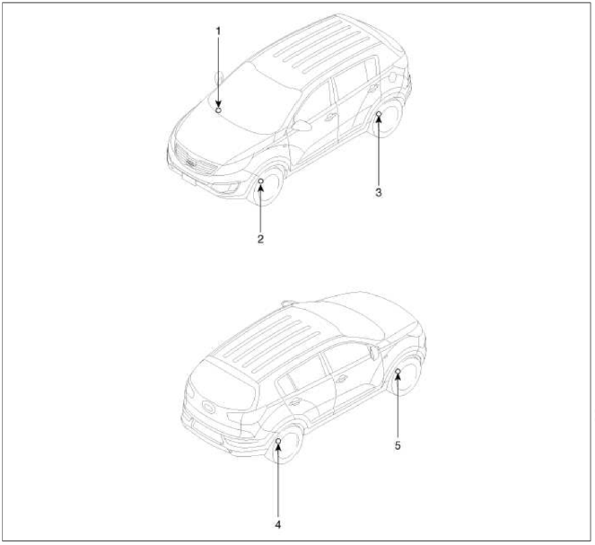
- Receiver
- TPMS Sensor
- TPMS Sensor
- TPMS Sensor
- TPMS Sensor
Description and Operation
Description
TREAD Lamp
- Tire Under Inflation / Leak Warning.

1. Turn on condition
- When tire pressure is below allowed threshold
- When rapid leak is detected by the sensor.
- Indicates that the needs to be re-inflated to placard pressure / repaired.
2. Turn off condition
- Under-inflation; When tire pressure is above (warning threshold + hysteresis).
- Rapid Leak; When the pressure is above (leak warning threshold).
DTC Warning
1. Turn on condition
- When the system detects a fault that is external to the receiver/ sensor.
- When the system detects a receiver fault.
- When the system detects a sensor fault.
2. Turn off condition
- If the fault is considered as 'critical', then the lamp is held on throughout the current Ignition cycle (even if the DTC has been de-activated). This is because it is important to bring the problem to the drivers attention. On the following Ignition cycle, the de-activated conditions will be re-checked. If the de-activate conditions occur, the lamp will be turned off. It will be held on until DTC demotion checking is completed.
- 'Non critical' faults are those that can occur temporarily e.g. vehicle battery under voltage. The lamp is therefore turned off when the DTC demotion condition occurs.
System Fault
1. General Function
- The system monitors a number of inputs across time in order to determine that a fault exists.
- Faults are prioritized according to which has the most likely cause.
- Maximum fault stored is equal to 15.
- Certain faults are not covered through DTC. The main ones are:
- Sensor thermal shutdown (over 257ºF/125ºC).
- Ignition Line stuck; requires observation of lamps at Ignition ON to diagnose.
READ NEXT:
 TPMS Sensor
Description and Operation
Description
1. Mode
Configuration State
All sensors should be in the Low Line (Base) state.
In Low Line (Base) configuration, sensor transmissions occur e
TPMS Receiver
Components and
Components Location
Components
TPMS Receiver Circuit Diagram
Harness Connector
Battery
CAN_High
GND
-
-
-
IGN
CAN_Low
-
-
-
-
Description and
SEE MORE:
General Information
Specifications
Specification
Tightening torque
CAUTION
Replace self-locking nuts with new ones after removal brake.
Lubricants
Special Service Tools
Special Service Tools
Troubleshooting
Troubleshooting
General Information, Specifications, Special Service Tools
General Information
General Information
The supplemental restraint system (SRS) is designed to supplement the seat
belt to help reduce the risk or severity
of injury to the driver and passenger by activating and deploying the driver,
passenger, side air bag and belt
pretensioner in cer
Content
- Home
- Kia Sportage - Fifth generation (NQ5) - (2022-2025) - Owner's Manual
- Kia Sportage - Second generation (JEKM) (2005-2015) - Body Workshop Manual
- Kia Sportage Third generation (SL) - (2011-2016) - Service and Repair Manual
- Sitemap
- Top articles
