Kia Sportage: General Information, Specifications, Special Service Tools
General Information
General Information
The supplemental restraint system (SRS) is designed to supplement the seat belt to help reduce the risk or severity of injury to the driver and passenger by activating and deploying the driver, passenger, side air bag and belt pretensioner in certain frontal or side collisions.
The SRS (Air bag) consists of; a driver side air bag module located in the center of the steering wheel, which contains the folded cushion and an inflator unit; a passenger side airbag module located in the passenger side crash pad contains the folded cushion assembled with inflator unit; side airbag modules located in the front seat contain the folded cushion and an inflator unit; curtain air bag modules located inside of the headliner which contains folded cushions and inflator units. The impact sensing function of the SRSCM is carried out by electronic accelerometer that continuously measure the vehicle's acceleration and delivers a corresponding signal through amplifying and filtering circuitry to the microprocessor.
SRSCM (SRS Control Module)
SRSCM will detect front impact with front impact sensor, and side impact with side impact sensor, and determine airbag module deployment.
1. DC/DC converter: DC/DC converter in power supply unit includes up/down transformer converter, and provide ignitron voltage for 2 front air bag ignitron circuits and the internal operation voltage of the SRSCM. If the internal operation voltage is below critical value setting, it will perform a reset.
2. Back up power supply: SRSCM has separate back up power supply, that will supply deployment energy instantly in low voltage condition or upon power failure by front crash.
3. Self diagnosis: SRSCM will constantly monitor current SRS operation status and detect system failure while vehicle power supply is on, system failure may be checked with trouble codes using GDS.
4. Airbag warning lamp on: Upon detecting error, the module will transmit signal to SRSCM indicator lamp located at cluster. MIL lamp will indicate driver SRS error. Upon ignition key on, SRS lamp will turn on for about six seconds.
5. Trouble code registration: Upon error occurrence in system, SRSCM will store DTC corresponding to the error.
DTC can be cleared only by GDS. However, if an internal fault code is logged or if a crash is recorded the fault clearing should not happen.
6. Self diagnostic connector: Data stored in SRSCM memory will be output to GDS or other external output devices through connector located below driver side crash pad.
7. Once airbag is deployed, SRSCM should not be used again but replaced.
8. SRSCM will determine whether passenger put on seat belt by the signal from built-in switch in seat belt buckle, and deploy front seat airbag at each set crash speed.
9. Side airbag deployment will be determined by SRSCM that will detect satellite sensor impact signal upon side crash, irrespective to seat belt condition.
10. Vehicle on an even surface not to be damaged the rollover sensor.
Ignition switched off during the SRSCM repair procedure.
11. Check for the normal operation of SRSCM after repair procedure.
Specifications
Specifications

Tightening Torques

Special Service Tools
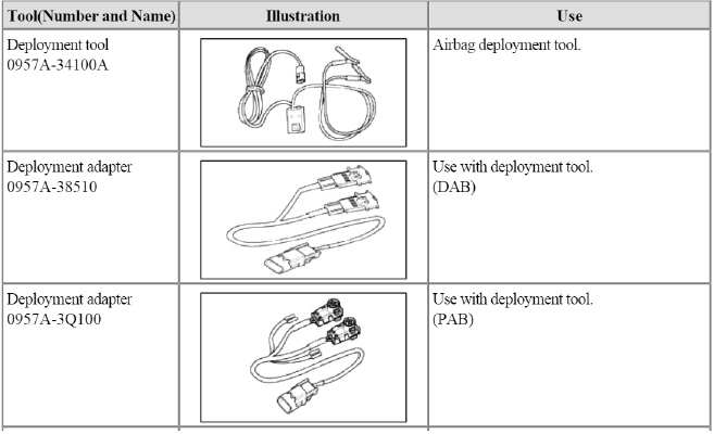
Special Service Tools


DAB : Driver Airbag
PAB : Passenger Airbag
SAB : Side Airbag
CAB : Curtain Airbag
BPT : Seat Belt Pretensioner
APT : Anchor Pretensioner
READ NEXT:
 General Safety Information and Caution
Precautions
General Precautions
Please read the following precautions carefully before performing the airbag
system service.
Observe the instructions described in this manual, or the airbag
 Description and Operation
Warning Lamp Activation
Warning Lamp Behavior after Ignition On
As soon as the operating voltage is applied to the SRSCM ignition input, the
SRSCM activates the warning lamp for
a LED lamp check.
 Repair procedures | Components and Components Location
Component Replacement After Deployment
NOTE
Before doing any SRS repairs, use the GDS Pro to check for DTCs. Refer to the Diagnostic Trouble Code list for repairing of the related DTCs.
When the f
SEE MORE:
 Anti-lock Brake System (ABS)
The Anti-lock Brake System (ABS) prevents
the wheels from locking. So the
vehicle remains stable and can still be
steered.
ABS (or ESC) will not prevent accidents
due to improper or dangerous driving
maneuvers. Even though vehicle control
is improved during emergency braking,
always mainta
 Defogging logic
To reduce the possibility of fogging up
the inside of the windshield, the air
intake or air conditioning is controlled
automatically according to certain conditions
such as
or
position.
To cancel automatic defogging logic or
return to the automatic defogging logic,
do the followi
Content
- Home
- Kia Sportage - Fifth generation (NQ5) - (2022-2025) - Owner's Manual
- Kia Sportage - Second generation (JEKM) (2005-2015) - Body Workshop Manual
- Kia Sportage Third generation (SL) - (2011-2016) - Service and Repair Manual
- Sitemap
- Top articles