Kia Sportage: Warning messages
The Auto Hold function will display a warning message with sound under certain conditions.
When the EPB is applied from Auto Hold,
a warning will sound and a message will
appear.
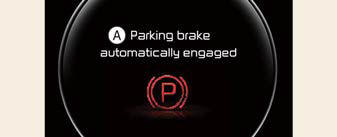
- Parking brake automatically engaged
When the conversion from Auto Hold to
EPB is not working properly a warning
will sound and a message will appear.
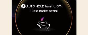
- AUTO HOLD turning Off! Press brake pedal
NOTICE
When this message is displayed, the Auto Hold and EPB may not operate. For your safety, press the brake pedal.
If you do not apply the brake pedal
when you release the Auto Hold by
pressing the [AUTO HOLD] switch, a
warning will sound and a message will
appear.
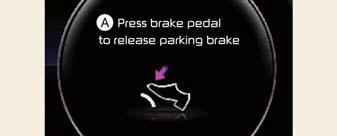
- Press brake pedal to deactivate AUTO HOLD
When you press the [AUTO HOLD]
switch, if the driver's door and engine
hood are not closed, a warning will
sound and a message will appear on the
LCD display.

- AUTO HOLD conditions not met.
Close door, hood and liftgate
At this moment, press the [AUTO HOLD] button after closing the driver's door and engine hood.
READ NEXT:
 Anti-lock Brake System (ABS)
The Anti-lock Brake System (ABS) prevents
the wheels from locking. So the
vehicle remains stable and can still be
steered.
ABS (or ESC) will not prevent accidents
due to improper or dangerous d
Electronic Stability Control (ESC) system
The Electronic Stability Control (ESC) is
designed to stabilize the vehicle during
cornering maneuvers.
ESC applies the brakes on individual
wheels and intervenes with the vehicle
management
Downhill Brake Control (DBC)
The Downhill Brake Control (DBC) feature
assists the driver to descend down a
steep hill without having to depress the
brake pedal.
The system automatically applies the
brakes to maintain t
SEE MORE:
Armed stage
Theft-alarm system
This system is designed to provide protection
from unauthorized entry into the
vehicle.
This system is operated in three stages:
Armed stage
Theft-alarm stage
Disarmed stage
If triggered, the system provides an
audible alarm with blinking of the hazard
warni
Description and Operation, Schematic Diagrams
Description and Operation
Description
The Evaporative Emission Control System prevents fuel vapor stored in fuel
tank from vaporizing into the
atmosphere. When the fuel evaporates in the fuel tank, the vapor passes through
vent hoses or tubes to a canister
filled with charcoal.
The
Content
- Home
- Kia Sportage - Fifth generation (NQ5) - (2022-2026) - Owner's Manual
- Kia Sportage - Second generation (JEKM) (2005-2015) - Body Workshop Manual
- Kia Sportage Third generation (SL) - (2011-2016) - Service and Repair Manual
- Sitemap
- Top articles
