Kia Sportage: Propeller Shaft Assembly
Propeller Shaft
Components and Components Location
Components
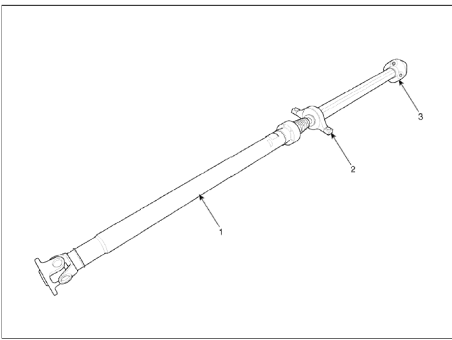
- Front propeller shaft
- Center bearing bracket
- Rear propeller shaft
Repair procedures
Replacement
1. After making a match mark on the flange yoke and transaxle companion, remove the propeller shaft mounting bolts.
Tightening torque: 49.0 ~ 68.6N.m (5.0 ~ 7.0kgf.m, 36.1 ~ 50.6lb-ft)

2. Remove the center bearing bracket (A) mounting bolts.
Tightening torque: 49.0 ~ 68.6N.m (5.0 ~ 7.0kgfm, 36.1 ~ 50.6lb-ft)

3. After making a match mark on the flange yoke and transaxle companion, remove the propeller shaft mounting bolts.
Tightening torque: 49.0 ~ 68.6N.m (5.0 ~ 7.0kgfm. 36.1 ~ 50.6lb-ft)

CAUTION
Use the hexagonal wrench to prevent damage of bolt head when removing bolts.
4. Install in the reverse order of removal.
Inspection
CV Joint and boots
1. Shift the transmission lever to Neutral.
2. Raise the vehicle off the ground, and support it with safety stands in the proper locations.
3. Check the center bearing for excessive play or rattle and rubber for rent. If the center bearing has excessive play or rattle and rubber has rent, replace the propeller shaft assembly.

4. Check the CV joint boot for damage and deterioration. If the boot is damaged or deteriored, replace the propeller shaft assembly.
5. Check the CV joint for excessive play or rattle. If the CV joint has excessive play or rattle, replace the propeller shaft assembly.
Propeller shaft runout
1. Install a dial indicator with its needle on the center of front propeller shaft or rear propeller shaft.
2. Turn the propeller shaft slowly and check the runout. Repeat this procedure for the other propeller shaft.
Front Propeller Shaft Runout: 0.3mm (0.012in.)

Rear Propeller Shaft Runout: 0.3mm (0.012m.)

3. If the runout on either propeller shaft exceeds the service limit, replace the propeller shaft assembly.
READ NEXT:
 Components and Components Location | Repair procedures
Component
Drive pinion nut
Oil seal
O-ring
Oil seal
Front bearing
Spacer
Rear bearing
Inner shim
Drive pinion gear
Differential carrier
SEE MORE:
Lane Keeping Assist malfunction and limitations
Lane Keeping Assist malfunction
Check Lane Safety system
When Lane Keeping Assist is not working
properly, the warning message will
appear and the yellow ( ) indicator
light will appear on the cluster. If this
occurs, have the function inspected by
an authorized Kia dealer.
Limitati
Seat belt - Driver's 3-point system with emergency locking retractor
The following explains how to fasten and
adjust the driver's seat belt.
Fastening the your seat belt:
Pull it out of the retractor
and insert
the metal tab (1) into the buckle (2).
There will be an audible "click" when
the tab locks into the buckle.
WARNING
You sh
Content
- Home
- Kia Sportage - Fifth generation (NQ5) - (2022-2025) - Owner's Manual
- Kia Sportage - Second generation (JEKM) (2005-2015) - Body Workshop Manual
- Kia Sportage Third generation (SL) - (2011-2016) - Service and Repair Manual
- Sitemap
- Top articles
