Kia Sportage: PDM Relay Box
Components and Components Location
Components
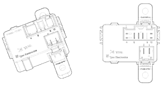
 Connector A (10 pins)
- Smart key unit
- -
- Ground
- Smart key unit
- -
- ACC
- Battery power (IGN-1)
- IGN-1
- -
- Smart key unit
 Connector Ð’ (2 pins)
- IGN-2
- Battery power (IGN-2)
Description and Operation
Description
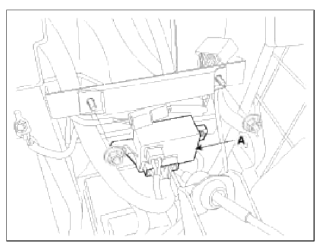
The PDM relay (A) is united with IG1, IG2 and ACC relays and installed in the lower center fascia panel.

Repair procedures
Removal
PDM Relay
1. Disconnect the negative (-) battery terminal.
2. Remove the floor console assembly.
(Refer to BD group - "Console")
3. Remove the PDM relay box (A) after loosening the bolts (2EA) and disconnecting the connector.

Installation
1. Install the PDM relay box.
2. Install the floor console assembly.
3. Connect the battery (-) cable.
Inspection
IG2 Relay
Check for continuity between the terminals.
1. There should be continuity between the No.1 and No.2 terminals in the Ð’ connector when power and ground are connected to the No.3 and No.4 terminals in the A connector.
2. There should be no continuity between the No.1 in the Ð’ and No.2 terminals in the Ð’ terminals when power is disconnected.
IG1 Relay
Check for continuity between the terminals.
1. There should be continuity between the No.7 and No.8 terminals in the A connector when power and ground are connected to the No.3 and No.10 terminals in the A connector.
2. There should be no continuity between the No.7 in the A and No.8 terminals in the A terminals when power is disconnected.
ACC Relays
Check for continuity between the terminals.
1. There should be continuity between the No.7 and No.6 terminals in the A connector when power and ground are connected to the No.1 and No.3 terminals in the A connector.
2. There should be no continuity between the No.7 in the A and No.6 terminals in the A terminals when power is disconnected.
READ NEXT:
 Components and Components Location | Instrument Cluster
Component Location
Cluster assembly
Seat belt switch
Vehicle speed sensor
Engine coolant temperature sender
Oil pressure switch
Brake fluid level warning swit
SEE MORE:
Mechanical key
If the smart key does not operate normally,
you can lock or unlock the door
by using the mechanical key.
To remove the
mechanical key, press
and hold the release button (1) and
remove the mechanical key (2).
To reinstall the mechanical key, put the
key into the hole and push it until a
ICM (Integrated Circuit Module) Relay Box
Components and Components Location
Component
Pin Information
Rear wiper motor
(Power)
IPM
Stop lamp
-
ESC unit
U_H_Box (ABS 7.5A
fuse)
Stop lamp switch
Stop lamp 10A fuse
-
-
IPM (Rear wiper 15 A)
Rear wiper motor
(Signal)
-
-
GND
IPM (BCM)
IPM (Do
Content
- Home
- Kia Sportage - Fifth generation (NQ5) - (2022-2026) - Owner's Manual
- Kia Sportage - Second generation (JEKM) (2005-2015) - Body Workshop Manual
- Kia Sportage Third generation (SL) - (2011-2016) - Service and Repair Manual
- Sitemap
- Top articles
