Kia Sportage: Installation - Repair procedures
Installation
1. Install the balance shaft chain. (Refer to Lubrication system in this group)
2. Install the crankshaft chain sprocket (B) and the timing chain oil jet (A).
Tightening torque: 7.8 ~ 9.8N.m (0.8 ~ 1.0kgf.m, 5.8 ~ 7.2lb-ft)

3. Set the crankshaft so that the key (A) of crankshaft will be aligned with the mating surface of main bearing cap.
Put the intake and exhaust camshaft assembly so that the TDC marks (B) of the intake and exhaust CVVT sprockets will be aligned with the top surface of cylinder head. As a result of this, the piston of No.1 cylinder is placed at the top dead center on compression stroke.

4. Install the timing chain guide (A).
Tightening torque: 9.8 ~ 11.8N.m (1.0 ~ 1.2kgf.m, 7.2 ~ 8.7lb-ft)

5. Install the tuning chain. To install the timing chain with no slack between each shaft (cam, crank), follow the below procedure.
Crankshaft sprocket (A) → Tuning chain guide (B) → Intake CVVT sprocket (C) → Exhaust CVVT sprocket (D).

NOTE
The tuning marks of each sprocket should be matched with tuning marks (color link) of timing chain when installing the timing chain.
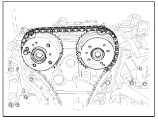

6. Install the timing chain tensioner arm (A).
Tightening torque: 9.8 ~ 11.8N.m (1.0 ~ 1.2kgf.m, 7.2 ~ 8.7lb-ft)

7. Install the timing chain auto tensioner (B) and remove the stopper pin (A).
Tightening torque: 9.8 ~ 11.8N.m (1.0 ~ 1.2kgf.m, 7.2 ~ 8.7lb-ft)

8. After rotating crankshaft 2 revolutions in regular direction (clockwise viewed from front), confirm that the TDC marks (A) on the intake and exhaust CVVT sprockets aligned with the top surface of cylinder head.

9. Install the timing chain cover.
- Using a gasket scraper, remove all the old packing material from the gasket surfaces.
- The sealant locations on chain cover and on counter parts (cylinder head, cylinder block, and ladder frame) must be free of engine oil and etc.
- Before assembling the timing chain cover, liquid sealant Loctite 5900H or equivalent should be applied on the gap between cylinder head and cylinder block. The part must be assembled within 5 minutes after sealant was applied.
Bead width: 3.0mm (0.12in.)
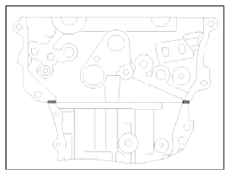
- After applying liquid sealant Loctite 5900H or equivalent on the timing
chain cover.
The part must be assembled within 5 minutes after sealant was applied. Continuous bead of sealant should be applied to prevent any path of oil leakage.
Bead width: 3.0mm (0.12in.)
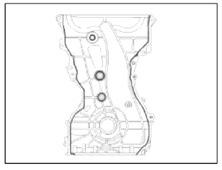
- The dowel pins on the cylinder block and holes on the timing chain cover should be used as a reference in order to assemble the timing chain cover to be in exact position.
Tightening torque:
Bolts A (M6x25): 7.8 ~ 9.8N.m (0.8 ~ 1.0kgf.m, 5.8 ~ 7.2lb-ft)
Bolts В (M8x28): 18.6 ~ 22.5N.m (1.9 ~ 2.3kgf.m, 13.7 ~ 16.6lb-ft)

CAUTION
The engine stalling or pressure tests should not be performed within 30 minutes after the timing chain cover was assembled.
10. Install the engine support bracket (A).
Tightening torque:
M10 bolts: 39.2 ~ 44.1N.m (4.0 ~ 5.0kgf.m, 28.9 ~ 32.5lb-ft)
M8 bolts: 19.6 ~ 24.5N.m (2.0 ~ 2.5kgf.m, 14.5 ~ 18.1lb-ft)
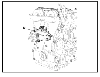
11. Install the crankshaft front oil seal (A) using SST (09214-3K000,09231-H1100) (B).

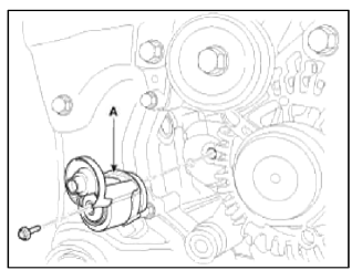
12. Install the drive belt tensioner (A).
Tightening torque: 53.9 ~ 63.7N.m (5.5 ~ 6.5kgf.m, 39.7 ~ 47.0lb-ft)
13. Install the idler (A), the water pump pulley (B), the crankshaft pulley (C) and the drive belt tensioner pulley (D).
Tightening torque:
Idler (A): 53.9 ~ 63.7N.m (5.5 ~ 6.5kgf.m, 39.7 ~ 47.0lb-ft)
Water pump pulley (B ): 7.8 ~ 9.8N.m (0.8 ~ 1.0kgf.m, 5.8 ~ 7.2lb-ft)
Crankshaft pulley (C): 166.6 ~ 176.4N.m (17.0 ~ 18.0kgf.m, 122.9 ~ 130.1lb-ft)
Drive belt tensioner pulley (D): 53.9 ~ 63.7N.m (5.5 ~ 6.5kgf.m, 39.7 ~ 47.0lb-ft)

CAUTION
Tensioner pulley bolt is left-handed screw.
NOTE
Use the SST (Ring gear stopper, 09231-2B100) to remove the crankshaft pulley bolt. Install the starter after installing the crankshaft pulley.

14. Install the engine mounting support bracket (B) and connect the ground line (A).
Tightening torque: 78.5 ~ 98.1 N.m (8.0 ~ 10.0 kgf.m, 57.9 ~ 72.3 lb-ft)

15. Remove the jack from the ladder frame.
16. Install the oil pan.
- Using a gasket scraper, remove all the old sealant material from the gasket surfaces.
- Before assembling the oil pan, liquid sealant Loctite 5900H. Threebond 1217H or equivalent should be applied on oil pan. The part must be assembled within 5 minutes after sealant was applied.
Bead width : 2.5mm (0.10in.)

CAUTION
- When applying sealant gasket, sealant must not be protruded into the inside of oil pan.
- To prevent leakage of oil, apply sealant gasket on the inner threads of the bolt holes.
- Install the oil pan (A). Uniformly tighten the bolts in several passes.
Tightening torque
Bolts В (M9): 30.4 ~ 34.3N.m (3.1 ~ 3.5kgf.m. 22.4 ~ 25.3lb-ft)
Bolts С (M6): 9.8 ~ 11.8N.m (1.0 ~ 1.2kgf.m, 7.2 ~ 8.7lb-ft)

CAUTION
After assembly, wait at least 30 minutes before filling the engine with oil.
NOTE
Always use a new drain plug gasket.
17. Install the А/С compressor bracket (A).
Tightening torque : 19.6 ~ 23.5N.m (2.0 ~ 2.4kgf.m, 14.5 ~ 17.4lb-ft)

18. Install the А/С compressor lower bolts (A).
Tightening torque : 20.0 ~ 33.0N.m (2.04 ~ 3.36kgf.m, 14.8 ~ 24.3lb-ft)

19. Install the drive belt (A).
Crankshaft pulley → А/С pulley → Alternator pulley → Idler #1 pulley → Idler #2 pulley → Water pump pulley → Tensioner pulley.
Rotate the drive belt tensioner arm (B) counterclockwise moving the tensioner pulley bolt with wrench. After putting the belt on the tensioner pulley, release the tensioner pulley slowly.

20. Install cylinder head cover.
- The hardening sealant located on the upper area between timing chain cover and cylinder head should be removed before assembling cylinder head cover.
- After applying sealant, it should be assembled within 5 minutes
Bead width : 2.5mm (0.10in.)
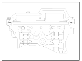
- Install the cylinder head cover (A) by tightening the bolts as following method.
Tightening torque
1st step: 3.9 ~ 5.9N.m (0.4 ~ 0.6kgf.m, 2.9 ~ 4.3lb-ft)
2nd step: 7.8 ~ 9.8N.m (0.8 ~ 1.0kgf.m, 5.8 ~ 7.2lb-ft)

CAUTION
- Do not reuse cylinder head cover gasket.
- The tiling and/or blow out test should not be performed within 30 minutes after the cylinder head cover was assembled.
21. Install the float engine hanger (B) and then connect the PCV (Positive crankcase ventilation) hose (A).
Tightening torque : 27.5 ~ 31.4N.m (2.8 ~ 3.2kgf.m, 20.3 ~ 23.1lb-ft)

22. Install the high pressure fuel pump (A) and the roller tappet (B). (Refer to FL group)
Tightening torque : 12.7 ~ 14.7N.m (1.3 ~ 1.5kgf.m, 9.4 ~ 10.8lb-ft)

CAUTION
Before installing the high pressure fuel pump, position the roller tappet in the lowest position (BDC) by rotating the crankshaft. Otherwise the installation bolts may be broken because of tension of the pump spring.
NOTE
Do not use already used bolt again.
NOTE
When tightening the installation bolts of the high pressure fuel pump, tighten in turn the bolts in small step (0.5 turns) after tightening them with hand-screwed torque.
CAUTION
Note that internal damage may occur when the component is dropped, hi this case, use it after inspecting.
NOTE
Apply engine oil to the О-ring (A) of the high pressure fuel pump, the roller tappet (B), and the protrusion (C). Also apply engine oil to the groove where the protrusion is installed.

23. Install the high pressure pipe (A). (Refer to FL group)
Tightening torque:
Bolt: 7.8 ~ 11.8N.m (0.8 ~ 1.2kgf.m, 5.8 ~ 8.7lb-ft)
Nuts : 26.5 ~ 32.4N.m (2.7 ~ 3.3kgf.m. 19.5 ~ 23.9lb-ft)

NOTE
Do not reuse the high pressure pipe.
24. Connect PCSV (Purge control solenoid valve) connector (A) and tighten the vacuum pipe assembly mounting bolts and nut.

25. Connect the fuel hose (A) and PCSV (Purge control solenoid valve) hose (B).

26. Install the ignition coils (A).
Tightening torque: 3.9 ~ 5.9N.m (0.4 ~ 0.6kgf.m, 2.9 ~ 4.3lb-ft)

27. Connect the ignition coil connectors (B) and fuel pump connector (A) after installing the wiring protector.

28. Connect the exhaust OCV (Oil control valve) connector (A) and the oxygen sensor connector (B).

29. Install the under cover (A).
Tightening torque: 7.8 ~ 11.8N.m (0.8 ~ 1.2kgf.m, 5.8 ~ 8.7lb-ft)

30. Install the intercooler inlet pipe & hose assembly (C) and then connect the recirculation valve connector (A) and the vacuum hose (B).
Tightening torque
Hose clamp bolt: 4.9 ~ 6.9 N.m (0.5 ~ 0.7 kgf.m, 3.6 ~ 5.1 lb-ft)
Pipe mounting bolt: 14.7 ~ 19.6 N.m (1.5 ~ 2.0 kgf.m. 10.8 ~ 14.5 lb-ft)

31. Install the RH front wheel.
32. Install the air cleaner assembly.
- Install the air cleaner assembly (F) and then connect the air intake hose (E).
Tightening torque
Hose clamp bolt: 2.9 ~ 4.9N.m (0.3 ~ 0.5kgf.m, 2.2 ~ 3.6lb-ft)
Ah cleaner assembly bolts: 7.8 ~ 9.8N.m (0.8 ~ 1.0kgf.m, 5.8 ~ 7.2lb-ft
- Connect the breather hose (B), the recirculation hose (C) and the brake booster vacuum hose (D).
- Install the air duct (A).

33. Connect the battery negative terminal (A).
Tightening torque: 4.0 ~ 6.0N.m (0.4 ~ 0.6kgf.m, 3.0 ~ 4.4lb-ft)

34. Install the engine cover.
35. Add all the necessary fluids and check for leaks. Connect GDS. Check for codes, note, and clear. Recheck.
NOTE
- Refill engine with engine oil.
- Refill a transaxle with fluid.
- Refill a radiator and a reservoir tank with engine coolant.
- Clean battery posts and cable terminals and assemble.
- Inspect for fuel leakage.
- After assemble the fuel line, turn on the ignition switch (do not operate the starter) so that the fuel pump runs for approximately two seconds and fuel line pressurizes.
- Repeat this operation two or three times, then check for fuel leakage at any point in the fuel line.
- Refill radiator and reservoir tank with engine coolant.
- Bleed air from the cooling system.
- Start engine and let it run until it warms up. (until the radiator fan operates 3 or 4 times.)
- Turn Off the engine. Check the level in the radiator, add coolant if needed. This will allow trapped air to be removed from the cooling system.
- Put radiator cap on tightly, then run the engine again and check for leaks.
READ NEXT:
 Camshaft
Repair procedures
Removal
Timing chain cover removal is not required for this procedure.
CAUTION
Use fender covers to avoid damaging painted surfaces.
To avoid damaging the cylinder hea
 Cylinder Head | Removal - Repair procedures - Cylinder Head
Components and Components Location
Components
Camshaft bearing cap
Camshaft front bearing cap
Exhaust camshaft
Intake camshaft
Exhaust CVVT assembly
Intake CVV
SEE MORE:
 Slide open/close
Push the sunroof switch rearward to
the first detent position, the sunroof
glass opens. However, if the power
sunshade is close, the power sunshade
will open first.
Push the sunroof switch forward to
the first detent position, the sunroof
glass closes. However, if the sunroof
 Torque Converter Control Solenoid Valve (T/CON_VFS) | 26 Brake Control Solenoid Valve (26/B_VFS)
Description and Operation
Description
Torque converter control solenoid valve (T/CON_VFS) is attached to the valve body. This variable force solenoid valve directly controls the hydraulic pressure inside the torque converter.
Specifications
Specifications
Direct control VFS [T/CO
Content
- Home
- Kia Sportage - Fifth generation (NQ5) - (2022-2025) - Owner's Manual
- Kia Sportage - Second generation (JEKM) (2005-2015) - Body Workshop Manual
- Kia Sportage Third generation (SL) - (2011-2016) - Service and Repair Manual
- Sitemap
- Top articles