Kia Sportage: Immobilizer Control Unit | Antenna Coil
Repair procedures
Removal
1. Disconnect the negative (-) battery terminal.
2. Remove the crash pad lower panel.
(Refer to the BD group - "Crash pad")
3. Remove the steering column assembly.
(Refer to the ST group - "steering column & shaft")
4. Disconnect the connector of the SMARTRA unit and then remove the SMARTRA unit (A) after loosening a bolt.
[USA]
![[Canada]](images/books/1921/13/index%2054.png)
[Canada]
Disconnect the connector of the SMARTRA unit (A) and then remove the bracket and immobilizer unit.

Installation
1. Install the immobilizer control unit after connecting the unit connector.
2. Install the steering column assembly.
3. Install the crash pad lower panel.
Antenna Coil
Repair procedures
Removal
1. Disconnect the negative (-) battery terminal.
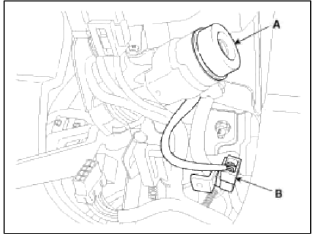
2. Remove the steering column upper and lower shrouds (A).

NOTE
Take care not to damage and scratch the shrouds and its related parts.
Take care not to damage the hook when removing the upper and lower shrouds.
3. Disconnect the 6P connector (B) of the coil antenna and then remove the coil antenna (A).
Installation
1. Install the coil antenna and connect the 6P connector.
2. Install the steering column upper and lower shrouds.
Troubleshooting
Diagnosis Of Immobilizer Faults
- Communication between the ECM and the SMARTRA.
- Function of the SMARTRA and the transponder.
- Data stored in the ECM related to the immobilizer function.
READ NEXT:
 Rear Parking Assist System Control Unit
Specifications
Specifications
The BCM contains the rear parking assist system function.
Components and Components Location
Component Location
First alarm: Object comes near to
SEE MORE:
Luggage net holder
To keep items from shifting in the cargo
area, you can use the 4 holders located
in the cargo area to attach the luggage
net (if equipped), or you can fold the
luggage net into half and attach it
upwards by using the additional 2 holders
located on each side.
If necessary, contact an auth
Cruise Control Switch
Schematic Diagrams
Circuit Diagram
[Auto Cruise Control]
Connector RH
ILL (-)
ILL (+)
-
-
-
ACC GND
ACC signal
ACC power
Repair procedures
Removal and Installation
1. Disconnect the battery (-) terminal.
Tightening torque:
Without battery sensor:
7.8 ~ 9.8N.m (
Content
- Home
- Kia Sportage - Fifth generation (NQ5) - (2022-2026) - Owner's Manual
- Kia Sportage - Second generation (JEKM) (2005-2015) - Body Workshop Manual
- Kia Sportage Third generation (SL) - (2011-2016) - Service and Repair Manual
- Sitemap
- Top articles
