Kia Sportage: Fuel Pump
Repair procedures
Inspection
[Fuel pump]
1. Turn the ignition switch OFF, and then remove battery (-) cable.
2. Remove the fuel pump assembly.
3. Check motor operation by fuel pump connector (A) connecting power (No.4) and ground (No.5).
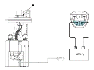
- -
- Fuel sender signal
- Fuel sender ground
- Fuel pump motor (+)
- Fuel pump motor ground
[Fuel sender]
1. Trim the ignition switch OFF, and then remove battery (-) cable.
2. Remove the fuel pump assembly.
3. Using an ohmmeter, measure the resistance between terminals 2 and 3 of sender connector (A) at each float level.
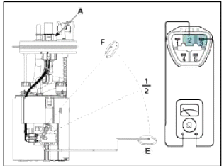
- -
- Fuel sender signal
- Fuel sender ground
- Fuel pump motor (+)
- Fuel pump motor ground
4. Also check that the resistance changes smoothly when the float is moved from "E" to "F".

Removal
1. Release the residual pressure in fuel line (Refer to "Release Residual Pressure in Fuel Line" in this group).
2. Remove the rear seat (Refer to "Seat" in BD group).
3. Remove the fuel pump service cover (A).

4. Disconnect the fuel pump connector (A) and the fuel tank pressure sensor connector (B).
5. Disconnect the fuel feed tube quick connector (C) and the vapor tube quick-connector (D).

6. Remove locking ring (A) by using the special service tool (B) [No.:09310-2S200].

Fuel pump locking ring loosening torque: Min. 68.65 M.m (Min. 7 kgf.m. Min. 50.6 lb-ft)
7. Remove the fuel pump from the fuel tank.

Installation
1. Installation is reverse of removal.
CAUTION
Be careful of fuel pump direction when installing (Refer to the groove in the fuel tank).
READ NEXT:
 Filler-Neck Assembly | Accelerator Pedal | Delivery Pipe
Repair procedures
Removal
1. Remove the rear-LH wheel, tire, and the inner wheel house.
2. Disconnect the fuel filler hose (A) and the ventilation hose (B).
3. Open the fuel filler door and unfa
SEE MORE:
Selecting a CRS
When selecting a CRS for your child,
always:
Make sure the CRS has a label certifying
that it meets applicable Federal
Motor Vehicle Safety Standards
(FMVSS 213).
Select a child restraint based on your
child's height and weight. The
required label or the instructions for
use t
Injector
Description and Operation
Description
Based on information from various sensors, the ECM can calculate the fuel
amount to be injected. The fuel injector
is a solenoid-operated valve and the fuel injection amount is controlled by
length of injection time. The ECM
controls each injector
Content
- Home
- Kia Sportage - Fifth generation (NQ5) - (2022-2025) - Owner's Manual
- Kia Sportage - Second generation (JEKM) (2005-2015) - Body Workshop Manual
- Kia Sportage Third generation (SL) - (2011-2016) - Service and Repair Manual
- Sitemap
- Top articles
