Kia Sportage: Fuel Pressure Control Valve | Electric WGT Control Actuator
Description and Operation
Description
Fuel Pressure Regulator Valve is installed on the high pressure fuel pump and controls fuel flow flowing into the injectors in accordance with the ECM signal calculated based on various engine condition.

Specifications
Specification

Troubleshooting
Signal Waveform

Schematic Diagrams
Circuit Diagram

Repair procedures
Inspection
1. Turn the ignition switch OFF and disconnect the battery negative (-) cable.
2. Disconnect the fuel pressure regulator valve connector.
3. Measure resistance between the fuel pressure regulator valve terminals 1 and 2.
4. Check that the resistance is within the specification
Specification: Refer to "Specification"
Removal
Refer to "High Pressure Fuel Pump" in this group.
Installation
Refer to "High Pressure Fuel Pump" in this group.
Electric WGT Control Actuator
Description and Operation
Description
The Electric WGT Control Actuator is installed on the turbocharger.
It operates the vain in the Waste Gate Turbocharger (WGT) and regulates the compressed air amount by the ECM's PWM signal. This actuator consists of a DC motor which actuates the vane, a 2-step gear which increases torque of the DC motor, a position sensor which detects status of the vane, an electric control unit which drives the DC motor.

Components and Components Location
Components
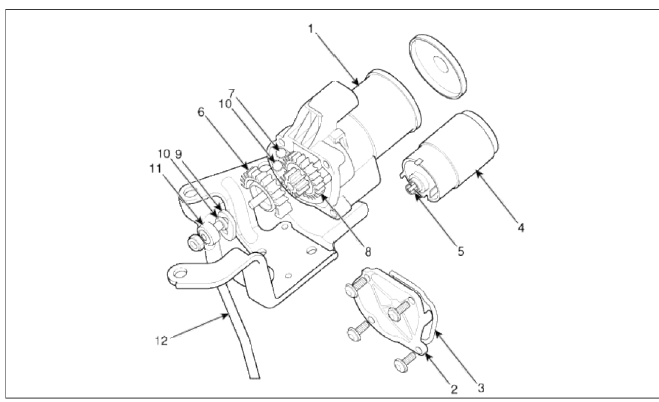
- Housing
- Cover
- Sealing Cover
- Motor
- Pinion
- Shaft Gear
- PCB Assembly
- Middle Gear
- Lever
- Lever Pin
- Rod - End
- Rod
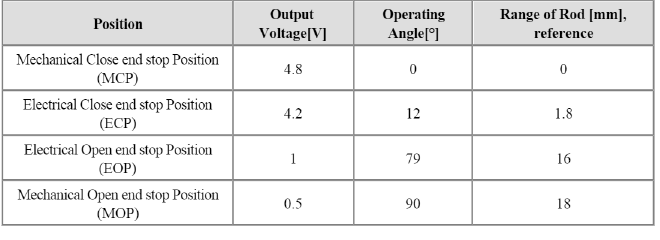
Specifications
Specification
[EWGA Position Sensor]
![[EWGA DC Motor]](images/books/1921/22/index%206.png)
[EWGA DC Motor]

Troubleshooting
Signal Waveform

Schematic Diagrams
Circuit Diagram

Repair procedures
Inspection
[Motor]
1. Turn ignition switch OFF.
2. Disconnect the EWGA connector.
3. Check that the EWGA is stuck by foreign material.
4. Measure resistance between motor (+) and (-) control terminals of the motor.
5. Check that the resistance is within the specification.
Specification: Refer to "Specification" section.
[Position Sensor]
1. Turn ignition switch ON.
2. Connect the GDS to the data link connector (DLC).
3. Check the output voltage at each position of the EWGA position sensor on current data item within the specification.
Specification: Refer to "Specification" section.
Removal
1. Turn the ignition switch OFF and disconnect the battery negative (-) cable.
2. Disconnect the EWGA connector (A).

3. Remove the shaft link assembly (B) after removing the C-ring (A).

4. Remove the EWGA after removing the bolts (A).

CAUTION
When carrying the turbo charger, do not hold the rod of the turbo charge to prevent bending the rod.
Installation
1. Installation is the reverse order of removal.
Adjustment
1. Turn ignition switch OFF.
2. Connect a GDS Data Link Connector (DLC).
3. Turn ignition switch ON.
4. Select "Current data".
5. Loosen the rod end lock nut (A) remove the C-ring (B).
6. Adjust the rod end part (C) by rotating it at the direction of clockwise or counter clockwise to satisfy the specification.
- If output voltage > 4.2 : Clockwise (D)
- If output voltage < 4.2 : Counter Clockwise (E
Specification : 4.2 +- 0.1V
7. Check output voltage on current data in GDS after installing the rod end part (C) without the clip.
If output voltage satisfy the specification, fix the rod end part with clip.

READ NEXT:
 RCV Control Solenoid Valve | Canister Close Valve (CCV)
Description and Operation
Description
RCV (Recirculation Valve) Control Solenoid Valve is installed on the intercooler inlet pipe and operates the RCV actuator which controls the by-pass pass
SEE MORE:
Camshaft
Repair procedures
Removal
Timing chain cover removal is not required for this procedure.
CAUTION
Use fender covers to avoid damaging painted surfaces.
To avoid damaging the cylinder head, wait until the engine coolant
temperature drops below normal
temperature before removing it.
Supplemental Restraint System (SRS) care
The Supplemental Restraint System
(SRS) is virtually maintenance-free and
so there are no parts you can safely service
by yourself.
If the SRS air bag warning light does not
appear, or continuously remains on,
have your vehicle immediately inspected
by an authorized Kia dealer.
Any work
Content
- Home
- Kia Sportage - Fifth generation (NQ5) - (2022-2025) - Owner's Manual
- Kia Sportage - Second generation (JEKM) (2005-2015) - Body Workshop Manual
- Kia Sportage Third generation (SL) - (2011-2016) - Service and Repair Manual
- Sitemap
- Top articles
