Kia Sportage: Components and Components Location | Power Door Lock Actuators
Component Location
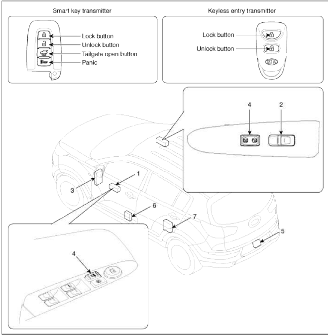
- Driver power window switch
- Assist power window switch
- SJB (Smart Junction Box)
- Door lock switch
- Tailgate lock actuator & switch
- Front door lock actuator & switch
- Rear door lock actuator & switch
Power Door Lock Actuators
Repair procedures
Inspection
Front Door Lock Actuator
1. Remove the front door trim.
(Refer to the BD group - "Front door")
2. Remove the front door module.
(Refer to the BD group - "Front door")
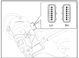
3. Disconnect the connectors from the actuator.

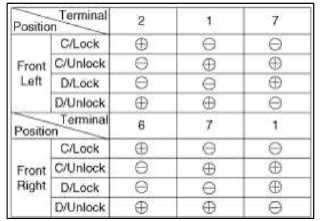
4. Check actuator operation by connecting power and ground according to the table. To prevent damage to the actuator, apply battery voltage only momentarily.
[Central Lock]
![[Double Lock]](images/books/1921/11/index%201.png)
[Double Lock]
Rear Door Lock Actuator
1. Remove the rear door trim.
(Refer to the BD group - "Rear door")
2. Remove the rear door module.
(Refer to the BD group - "Rear door")
3. Disconnect the connectors from the actuator.
4. Check actuator operation by connecting power and ground according to the table. To prevent damage to the actuator, apply battery voltage only momentarily.
[Central Lock]
![[Double Lock]](images/books/1921/11/index%204.png)
[Double Lock]

Tailgate Lock Actuator Inspection
1. Remove the tailgate trim.
(Refer to the BD group - "Tailgate")
2. Disconnect the 4P connector from the actuator.

3. Check actuator operation by connecting power and ground according to the table. To prevent damage to the actuator, apply battery voltage only momentarily.

Front Door Lock Switch
1. Remove the front door trim.
(Refer to the BD group - "Front door")
2. Remove the front door module.
(Refer to the BD group - "Front door")
3. Disconnect the connectors from the actuator

4. Check for continuity between the terminals in each switch position when inserting the key into the door according to the table.
[Central Lock]
![[Double Lock]](images/books/1921/11/index%209.png)
[Double Lock]

Rear Door Lock Switch
1. Remove the rear door trim.
(Refer to the BD group - "Rear door")
2. Remove the rear door module.
(Refer to the BD group - "Rear door")
3. Disconnect the connectors from the actuator.
4. Check for continuity between the terminals in each switch position according to the table.
[Central Lock]

Tailgate Switch
1. Remove the tailgate trim.
(Refer to the BD group - "Tailgate")
2. Disconnect the 4P connector from the actuator.

3. Check for continuity between the terminals in each switch position according to the table.

READ NEXT:
 Power Door Lock Switch
Repair procedures
Inspection
Driver Power Door Lock Switch
1. Disconnect the negative battery terminal.
2. Remove the front door trim.
(Refer to the BD group - "Front door")
Power Door Mirrors
Components and Components Location
Component Location
Power door mirror
Power door mirror
switch
Power Door Mirror Switch
Schematic Diagrams
Circuit Diagram
Connecto
SEE MORE:
Rear Seat
Components and Components
Location
Components
Headrest
Headrest guide
Tether anchor garnish
Upper bezel
Rear seat back pad
Latch cover
Rear seat back cover
Armrest board
Rear armrest
Rear seat back frame
Rear seat cushion cover
Rear seat cushion warmer
Rear seat
Smart key immobilizer system
The immobilizer system protects your
vehicle from theft. If an improperly
coded key (or other device) is used, the
vehicle's power system is disabled.
When the ENGINE START/STOP button
is placed in the ON position, the immobilizer
system indicator should come on
briefly, then go off. If
Content
- Home
- Kia Sportage - Fifth generation (NQ5) - (2022-2026) - Owner's Manual
- Kia Sportage - Second generation (JEKM) (2005-2015) - Body Workshop Manual
- Kia Sportage Third generation (SL) - (2011-2016) - Service and Repair Manual
- Sitemap
- Top articles
