Kia Sportage: Climate Seat
Components and Components Location
Components
[Front Seat]
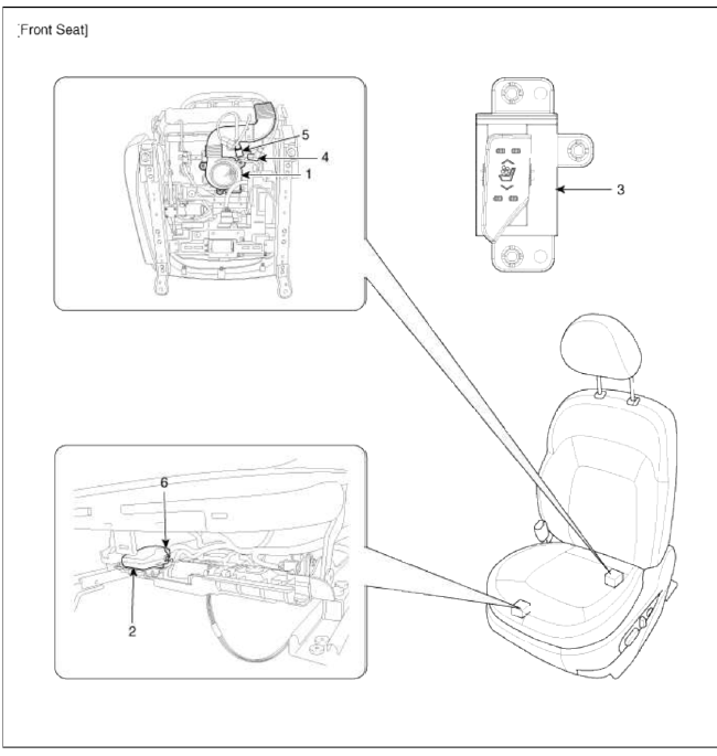
- Ventilation blower
- Ventilation ECU
- Ventilation seat switch
- Blower connector
- Heater connector
- Ventilation ECU connector
Schematic Diagrams
Schematic Diagram
[Front Seat]

Connector Configurations
 Blower connector
- -
- Blower B+
- Blower speed control
- Blower ground
- -
 Heater connector
- -
- NTC ground
- Vent B+
- Heater mat 2
- Heater mat 1
- NTC
 Ventilation control unit connector
- NTC ground
- Vent indicator (Low)
- Heater indicator (Low)
- Blower speed control
- Vent switch
- Blower B+
- IGN 1
- Vent ground
- NTC
- Vent indicator (High)
- Heater indicator (High)
- -
- Heater switch
- Blower ground
- Heater mat 2
- Heater mat 1
Description and Operation
Description
The system uses a FAN under the seat to help remove the moisture and warmth from occupants and surface of the seats.
It pulls in cabin air though the blower installed under the seat cushion, and supplies the air into the seat cushion and the seat back through the duct.
CAUTION
1. Make sure not to spill liquid on the seat when equipping with ventilation system seats.
2. Because the ventilation system does not move great amounts of air, it is difficult to feel the air coming though the seat cover.
Repair procedures
Removal
1. Remove the front seat assembly.
(Refer to BD group - "Front Seat")
2. Remove the seat back cover and cushion cover.
(Refer to BD group - "Front Seat")
3. Remove the ventilation duct (A) from the seat back after loosening the screw and rivet.

4. Remove the ventilation duct and blower (A) in the cushion and back after loosening the screw.

5. Remove the bracket and ventilation seat ECU (B) after loosening screws (A, 3EA).

Installation
1. Install the connectors and air ventilation control unit.
2. Install the air ventilation duct and blower.
3. Install the seat back cover.
4. Install the seat assembly and seat hack cover.
READ NEXT:
 Components and Components Location | Relay Box (Engine Compartment)
Component Location
[Engine Room Relay Box]
Main relay
Cooling fan relay (High)
Windshield deicer relay
Wiper relay (High)
Wiper relay (Low)
ATM relay
Rear
SEE MORE:
Emergency starting
When the vehicle will not start because
of low battery power, you may need to
jump start the vehicle.
Jump-starting
Connect cables in numerical order and
disconnect in reverse order.
Jump-starting can be dangerous if done
incorrectly. Therefore, to avoid harm to
yourself or damage to you
Windshield Glass
Components and Components Location
Components
Windshield side
molding
Windshield glass
Repair procedures
Replacement
Removal
CAUTION
Put on gloves to protect your hands.
Use seat covers to avoid damaging any surfaces
1. Remove the following items
Front pilla
Content
- Home
- Kia Sportage - Fifth generation (NQ5) - (2022-2025) - Owner's Manual
- Kia Sportage - Second generation (JEKM) (2005-2015) - Body Workshop Manual
- Kia Sportage Third generation (SL) - (2011-2016) - Service and Repair Manual
- Sitemap
- Top articles
